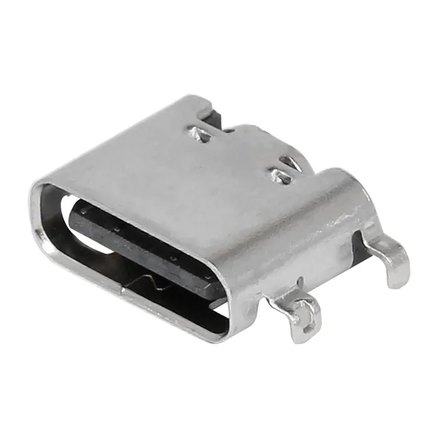
USB-C Receptacle for Board-Edge Integration
It carries 24 contacts — 16 for the standard USB-C signal and power interface, plus 8 dummy pins that provide mechanical stability during the reflow process and in the mated joint.
What the Contact Ratings Mean for Your Circuit
The current rating is split across the contact groups: 0.25 A on the signal pins, 1.25 A on the sideband pins, and 5 A on the power (VBUS/GND) contacts. This is a standard USB-C power profile. The 5 A path on the power contacts means the receptacle can handle the full USB-C current for charging or power delivery, but the total system current is limited by the cable and the source. The 0.25 A signal contacts are sized for the low-current control lines — do not route power through them. The 30 VAC/DC rating covers the VBUS voltage for standard USB power delivery up to 20 V.
Mating Cycles and Field Reliability
The shielded steel/stainless shell provides EMI containment for the USB 2.0 data lines in electrically noisy environments like industrial controllers or medical devices.
Mounting and Soldering Notes
This is a surface-mount, right-angle connector with a mid-mount feature — the receptacle body sits partially recessed into a cutout on the PCB edge, which lowers the overall height above the board. The mid-mount design is common for USB-C connectors to meet the slim profile requirements of modern enclosures.