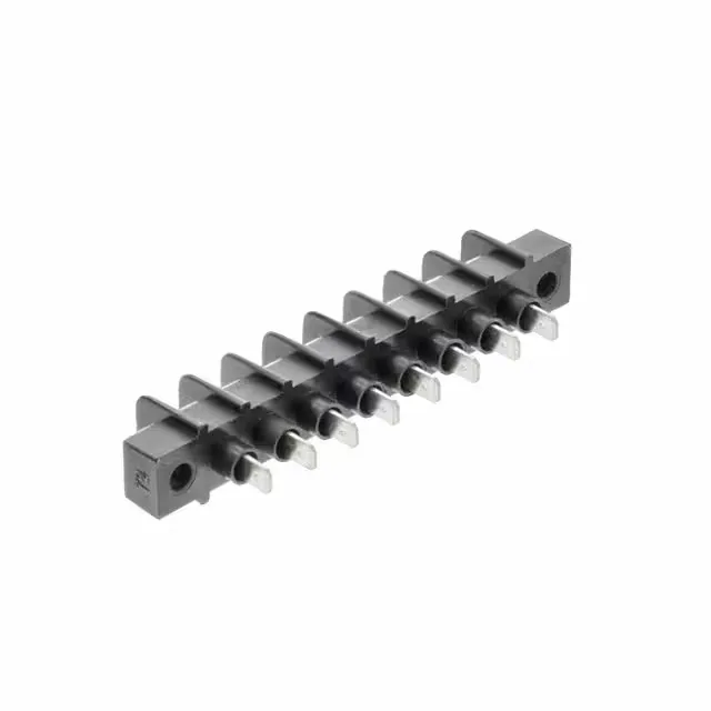
The 387216708: The 15 A per-circuit rating and 300 V voltage ceiling are the headline numbers for a barrier block of this size. The 15 A is a continuous rating at the full temperature range, not a peak — the PBT insulation and 0.375" pitch provide enough creepage for the 300 V without flashover across the terminals. The dual-wall barrier (2 Wall) between each circuit physically separates adjacent terminals, so a stray strand bridging two screws won't arc. The terminal screw finish is zinc clear chromate over steel — standard for corrosion resistance in a dry indoor panel, but if the environment sees condensation or washdown, the screw plating is not the weak point; the housing seal between circuits is.
Termination: top screw, bottom quick-connect
Top termination is screws — you land the field wire (14-22 AWG) under the clamp plate, no crimp tool needed. Bottom termination is an insulated 0.187" quick-connect tab, which means the factory harness or pre-terminated lead pushes onto the tab. That dual termination is the main feature: the screw side stays accessible for service or rewire while the bottom side is a fixed pigtail or bus connection. The flange mount with the two mounting ears secures the block to the chassis or panel — the screw holes are slotted for alignment tolerance.
The 387216708 is listed as Active on lifecycle status and ROHS3 Compliant.
8 circuits vs 6 circuits — same footprint, different density
The 387216708 (8 circuits) shares the same 0.375" pitch, 15 A rating, 300 V rating, dual-wall barrier, screw/quick-connect termination, and flange mount as the 6-circuit sibling 387216706. If the panel cutout was designed for the 6-circuit version, the 8-circuit will not fit without a longer opening; conversely, if the BOM calls for 8 positions, the 6-circuit is short by two circuits. Same series, same tooling, same installation method — the choice is purely the number of circuits the circuit count needs.