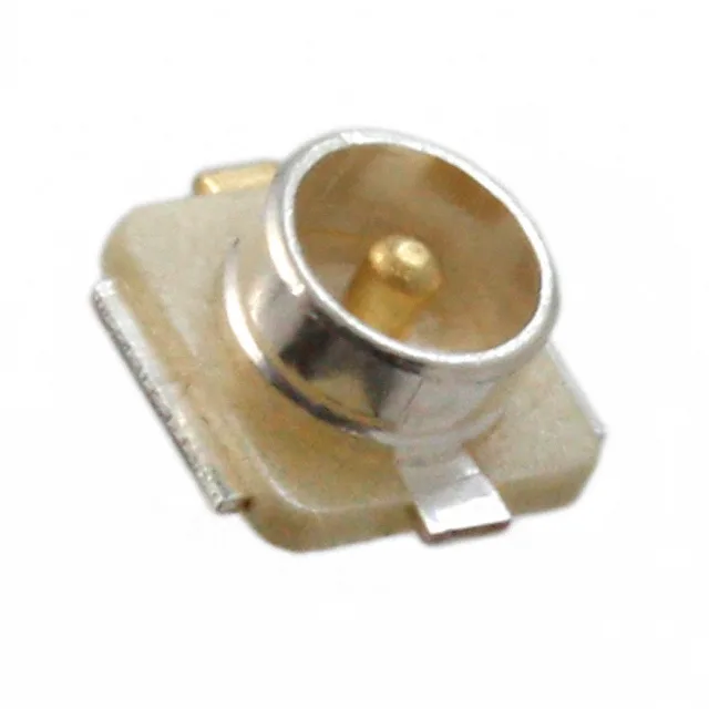
Hirose Electric Co Ltd C.FL-R-SMT-1(90) — RF Cable Assemblies

Hirose C.FL-R-SMT-1(90) Receptacle, 50 Ohm, 30 GHz

MPNC.FL-R-SMT-1(90)
Active

Hirose C.FL series ultra-miniature SMT receptacle, male pin, 50 Ohm, 30 GHz, snap-on, gold body, 1 port, Tape & Reel.

$1.6400Ref. price · indicative, final on quote
Sourced new & surplus through independent channelsAuthenticity-screened · ESD-safe packingListing updated Aug 2026

Specifications

C.FL-R-SMT-1(90) specifications
ParameterValue
SeriesC.FL
MountingSurface Mount
Connector typeReceptacle, Male Pin
Fastening typeSnap-On
Frequency - max30 GHz
Operating temperature-10°C ~ 40°C
Body materialPhosphor Bronze
Housing colorGold
Dielectric materialLiquid Crystal Polymer (LCP)
Center contact materialBrass
PackageTape & Reel (TR) Cut Tape (CT)
Impedance50 Ohms
Body finishGold
Mating cycles20
Number of ports1
Shield terminationSolder
Contact terminationSolder
Center contact platingGold

Product details

RF Interconnect for Tight Signal Paths

The C.FL-R-SMT-1(90): It sits in the C.FL series — Hirose's compact coaxial line — and is specified for 50 Ohm impedance with a frequency ceiling of 30 GHz. The gold-plated phosphor bronze body and brass centre contact with gold plating handle the signal path, while the liquid crystal polymer (LCP) dielectric keeps losses predictable through the 30 GHz band.

What the 30 GHz and 20-Cycle Ratings Mean

The 30 GHz maximum frequency is the headline spec here — it puts this C.FL receptacle well above the 6 GHz ceiling of the sibling X.FL series. That frequency rating means the connector maintains a controlled 50 Ohm impedance through the snap-on interface up to mmWave bands, suitable for 5G NR FR2, microwave backhaul, or high-speed digital test points. The 20 mating cycles are a hard limit: this is a limited-mate connector. Each snap-on engagement wears the gold-on-gold contact interface, and after 20 cycles the contact resistance rises beyond the design window. Plan this as a semi-permanent board-to-cable interconnect, not a frequent disconnect point. The shield termination is solder — the outer ground path is established through the solder pad, not a crimp ferrule, so the board footprint must include a solid ground plane return.

Frequently asked questions

Where can I buy the C.FL-R-SMT-1(90) and what is the lead time?

Submit an RFQ for your BOM quantity to get a firm lead time and price.

Is the C.FL-R-SMT-1(90) compatible with C.FL series plugs?

The snap-on fastening type and 50 Ohm impedance are consistent across the C.FL interface.

What is the impedance of C.FL-R-SMT-1(90)?

The C.FL-R-SMT-1(90) is specified at 50 Ohms impedance, the standard for RF transmission lines.