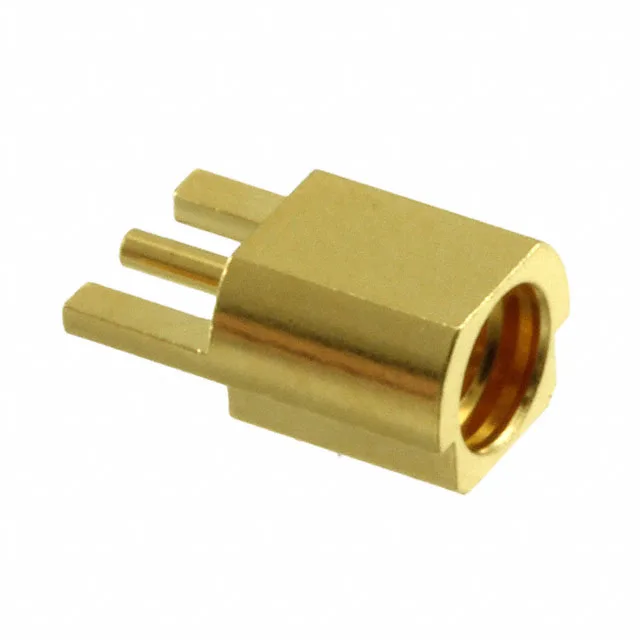
MMCX-LR-SMT(40) — 50 Ohm SMT Receptacle for Board-Edge RF
The board-edge cutout aligns the body flush with the board edge, keeping the signal path short and the impedance controlled through the launch.
What the 6 GHz and 500-Cycle Ratings Mean on the Bench
The 6 GHz max frequency is the usable bandwidth before return loss climbs above the interface spec — for a 50 Ohm system, that covers L-band, S-band, and most of C-band. If you're mating and unmating daily in a test fixture, 500 cycles is a reasonable service life before you swap the board-mounted jack. The SMT shield termination and contact termination mean the connector reflows with the board — no hand-soldering the ground legs. The board-edge cutout mount requires a slot in the PCB; the connector body drops into that cutout so the center contact aligns with the microstrip trace. Match the PCB footprint to the Hirose drawing, and the impedance through the launch stays at 50 Ohm.
The difference is the mounting: the MMCX-LR-SMT(40) is a board-edge cutout SMT part, while the MMCX-R-PC(40) is a through-hole PC-mount receptacle in bulk packaging. If your board has the edge cutout and you're reflowing, the LR-SMT is the one. If you're hand-soldering into a standard plated-through-hole pattern, the R-PC is the fit.