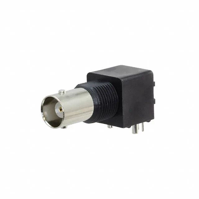
The 031-5538: The 1 GHz frequency ceiling and 0.2 dB insertion loss suit this jack for test equipment, instrumentation, and low-power RF links where the signal budget is tight.
The 50 Ohm impedance is non-negotiable for a 50 Ohm system — mismatched impedance at the RF connector interface will reflect power back up the cable. The 1 GHz maximum frequency covers composite video, GPS L-band, and most lab-grade signal generators; above 1 GHz the insertion loss and return loss degrade. The 0.2 dB insertion loss at the connector is low enough to ignore in a short cable run but adds up in a multi-connector chain. 500 mating cycles means this jack is designed for frequent connect/disconnect — think test bench or field deployable gear where the cable is swapped daily. The right-angle through-hole mounting with panel-mount bulkhead defines the PCB footprint: the connector body sits on the board edge, the centre pin solders into a plated through-hole, and the four ground legs solder to the board while the bulkhead flange seats against the panel.