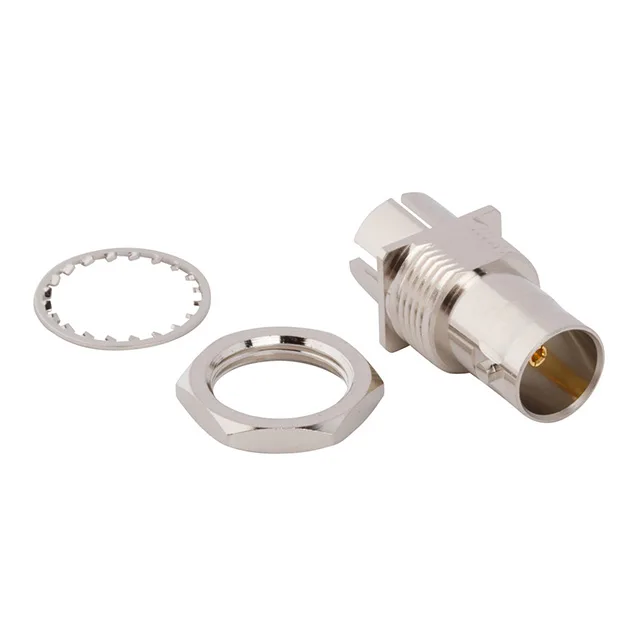
BNC Jack for 75 Ohm Systems — Board-Edge or Bulkhead
The 031-70526-11: The 75 Ohm impedance targets video, broadcast, and data-com applications — RG59, RG6, and similar 75 Ohm cable families — rather than the 50 Ohm world of test equipment and telecom. The nickel-plated brass body gives the shell a consistent ground reference and resists corrosion in indoor or sheltered outdoor enclosures.
Mounting Options — Board-Edge End Launch or Panel Feedthrough
The 031-70526-11 supports two mounting modes. For a PCB-edge RF launch, the end-launch solder terminals let the centre contact and shield solder directly to the board — the signal path stays short and the impedance transition is controlled. For a panel feedthrough, the bulkhead flange with front-side nut clamps the connector to a chassis or enclosure wall; the lockwasher prevents the nut from backing off under vibration. The bayonet lock (BNC standard) gives a quarter-turn mate that locks positively without threads — fast to connect and disconnect in the field, and the 500-cycle mating life means it holds up to regular service access.
What the 12 GHz Ceiling and 75 Ohm Mean for Your Signal Path
The 12 GHz frequency maximum is high for a 75 Ohm BNC — most 75 Ohm BNCs are specified to 1-4 GHz for video baseband. The 12 GHz rating means this jack supports higher-frequency modulated signals or digital data streams well beyond standard-definition video, though the usable bandwidth in a real system also depends on the cable and the mating plug's performance. The 75 Ohm impedance is non-negotiable for the system: a 75 Ohm jack on a 50 Ohm line creates a reflection at the junction. Match it with 75 Ohm cable and a 75 Ohm BNC plug.