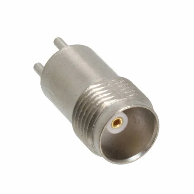
It is the 1-port member of the 031-71 base series, terminated by soldering the centre contact and shield to the board. The 75 Ohm impedance targets video distribution, CATV headends, and telecom baseband equipment where 50 Ohm would mismatch the line. Inside, the beryllium copper centre contact is gold-plated, giving 500 mating cycles — enough for test points or field-service connections that see repeated connect/disconnect without degrading signal quality.
Signal Path: 75 Ohm, 11 GHz, 0.18 dB Loss
Swapping it into a 50 Ohm line creates a mismatch that reflects signal and raises VSWR. The PTFE dielectric maintains consistent impedance through the interface, and the 0.18 dB insertion loss at 11 GHz means the connector contributes less than a fifth of a dB to the link budget at the top of its band. The 11 GHz maximum frequency covers the full operating range of most 75 Ohm video and data links, including DOCSIS 3.1 upstream bands and HD-SDI video. Below 3 GHz the loss is even lower — the 0.18 dB figure is the ceiling, not the floor.
Mechanical Fit: Threaded Fastening, Solder Termination
The threaded coupling (TNC standard) gives a vibration-resistant mate that won't back off under cable strain — a real advantage over bayonet-style BNC in equipment that gets moved or shipped. The through-hole solder termination requires the PCB to have plated holes for the centre pin and shield legs; no press-fit or crimp tooling needed on site. The 500-cycle mating life, backed by gold-on-beryllium-copper contacts, means this jack survives years of test-port use or field reconnections before the centre contact wears enough to shift impedance. When it does, the whole connector is replaced — the contact is not field-replaceable separately.