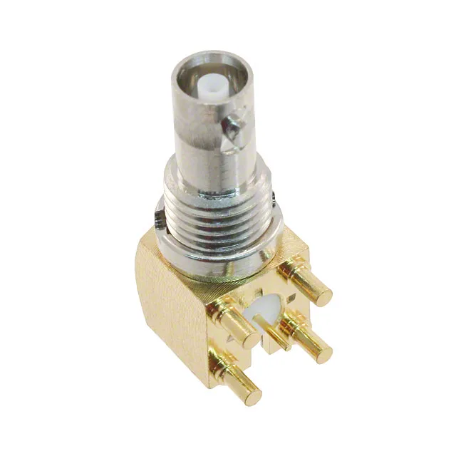
034-1030 — Amphenol product photo

Amphenol RF 034-1030 BNC HD Jack, 75 Ohm, 4.5 GHz

MPN034-1030
Active

Amphenol RF BNC HD jack, 034-1030, 75 Ohm impedance, 4.5 GHz max frequency, panel mount with right-angle solder termination, 1 port, bulkhead front-side nut, 500 mating cycles.

$11.2700Ref. price · indicative, final on quote
StockContact for availability
MOQ1 pcs
  • New & original stockTraceable channels only — no mixed lots, no re-taped reels.
  • Factory packaging where availableSealed reels, trays and bags; cut quantities always stated on the quote.
  • Photo-verified countsEvery line counted and photographed before the box closes.
  • PayPal buyer protectionPay by T/T, PayPal or Payoneer — card payments covered end to end.

Specifications

034-1030 Technical Specifications
ParameterValue
Mounting typePanel Mount, Through Hole, Right Angle
Connector typeJack, Female Socket
Fastening typeBayonet Lock
Frequency - max4.5 GHz
Mounting featureBulkhead - Front Side Nut
Operating temperature-65°C~165°C
Body materialBrass
Housing colorGold, Silver
Dielectric materialPolytetrafluoroethylene (PTFE)
Center contact materialBeryllium Copper
PackageBulk
Includes2 pcs - 1 Connector, 1 Nut
Impedance75Ohm
Body finishGold; Nickel
Mating cycles500
Number of ports1
Shield terminationSolder
Contact terminationSolder
Center contact platingGold

Product details

75 Ohm BNC HD Jack for High-Frequency Signal Paths

The 034-1030: This is the HD (high-density) variant of the standard BNC interface, offering improved electrical performance at higher frequencies while maintaining bayonet-lock compatibility with standard BNC plugs. The 75 Ohm impedance makes it the correct choice for video, broadcast, and telecommunications applications where 75 Ohm cabling is standard — not to be confused with the 50 Ohm BNC used in RF test and wireless infrastructure. The connector uses a beryllium copper center contact with gold plating, housed in a brass body with gold and nickel finishes.

Panel Mount Installation with Right-Angle Solder Tails

The right-angle through-hole solder termination means the signal pin exits perpendicular to the connector axis, routing the signal along the PCB rather than straight back. The shield termination is also solder-style, requiring a soldered ground connection to the board or chassis. For a clean RF launch, the PCB footprint should match the 75 Ohm trace impedance; the right-angle tail geometry introduces a small inductive discontinuity that must be accounted for in the layout above 2 GHz.

Frequently asked questions

Where can I buy the 034-1030 and what is the price?

The 034-1030 is sourced to order through independent distribution.

Is the 034-1030 50 Ohm or 75 Ohm?

The 034-1030 is a 75 Ohm BNC HD jack. This is the correct impedance for video, broadcast, and telecommunications signal paths. It will not properly terminate a 50 Ohm system — the impedance mismatch causes signal reflections and degrades return loss above a few hundred MHz.