Board Layout and Pitch Compatibility
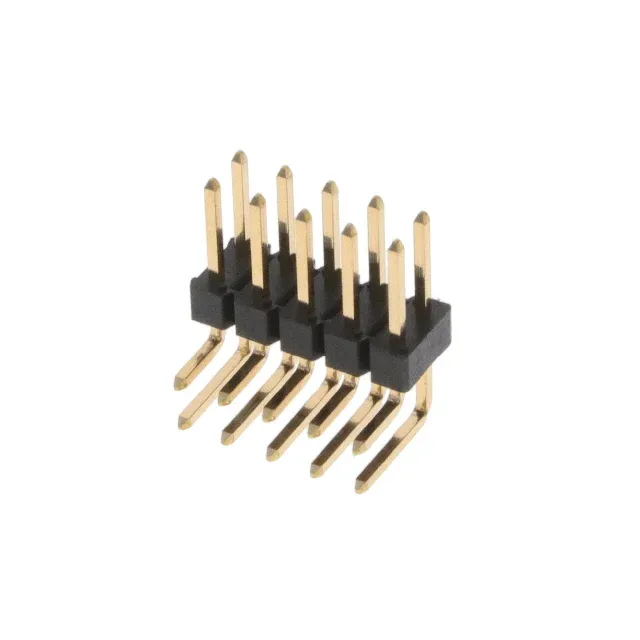
The 10129381-924003BLF: Dual-row layout doubles the signal density over a single-row header on the same board edge, which matters when routing traces between the rows on a two-layer PCB.
The mating surface carries 1.00 µinch (0.025µm) gold over copper alloy — a light flash finish. This is adequate for occasional reconnects (tens of cycles) in lab, test, or low-service applications. For field equipment cycled quarterly or in corrosive environments, a thicker gold (15 µinch or higher) would be the safer choice; this part is best suited for one-time assembly or infrequent disconnection. In a vibration environment, the mating pair can separate if the cable is tugged — a locking latch or shroud would add mechanical security. For bench-top or stationary equipment, this is rarely an issue.
Current and Voltage Ceilings
The 110 VDC voltage rating is a conservative creepage-and-clearance limit for the 2.54mm pitch and unshrouded layout. The lower bound suits cold storage or outdoor telecom cabinets; the upper bound is below the solder reflow peak but fine for wave-solder assembly.
Cuttable Header Flexibility
The connector type is listed as 'Header, Cuttable' — the 24-position strip can be broken to shorter lengths (e.g., 20, 16, 10 positions) using the snap-off grooves between positions. This lets one part number serve multiple BOM line items, reducing the number of unique SKUs in the storeroom. The break leaves a clean edge; the remaining pins retain full electrical and mechanical integrity.
Peer Comparison: 24 vs 20 Positions
The 10129381-920003BLF drops to 20 positions on the same dual-row layout. For a BOM that needs 20 circuits, the 24-position strip can be cut down; for 24 circuits, the 924001BLF is a drop-in if the shorter pin length fits the mating socket depth.