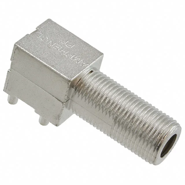
75 Ohm F-Type Jack for CATV and Satellite — Not Your Bench SMA
The 75 Ohm impedance tells you this is not a general-purpose RF connector; it is purpose-built for the video distribution chain where the characteristic impedance of the cable and the connector must match the head-end and set-top equipment. The right-angle through-hole mounting puts the signal path parallel to the board, so the cable exits the enclosure side — typical for wall-plate jacks, modem back panels, and satellite receiver rear panels.
What the 3 GHz Bandwidth and 500 Mating Cycles Tell You
Rated to 3 GHz, this jack covers the full L-band (950–2150 MHz) used by satellite IF, plus the entire CATV upstream and downstream spectrum. It stops short of the 6 GHz unlicensed band, so it is not a Wi-Fi 6E or 5G mmWave interconnect — it is a video/broadband component. The 500 mating cycles are standard for a threaded F-type; the tin-plated zinc body and steel threads will gall before the beryllium copper centre contact wears out.
Mounting and Termination — Solder the Shield, Solder the Pin
Both the shield and the centre contact terminate by solder — no crimp, no compression. The shield termination is a solder cup or tab (the spec lists shield termination as solder), and the centre contact is a solder cup on the beryllium copper pin. The right-angle body means the centre pin is perpendicular to the board edge; the footprint is a standard F-type through-hole pattern with the shield legs and centre pin on a 0.312-inch pitch typical for F jacks.