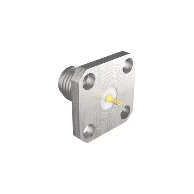
SMA Panel Jack for 18 GHz Signal Paths
The 901-2PB100000AE: Gold-plated beryllium copper centre contact and a threaded fastening type give this jack the mechanical repeatability for 500 mating cycles — a field-service life that covers most test-equipment, antenna, and instrumentation applications without premature contact wear.
The 18 GHz max frequency is the upper -3 dB point for this SMA jack — it means the connector maintains a 50 Ohm transmission line through the launch, so the signal sees no impedance bump that would cause reflections or insertion loss roll-off below that frequency. For sub-6 GHz work (cellular, Wi-Fi, GNSS) the margin is generous; for Ku-band satellite links or 5G mmWave test setups at 18 GHz, the connector is at its rated ceiling, so the PCB launch and cable assembly must match the 50 Ohm impedance to within a few percent. The 500 mating cycles are delivered by the gold-on-beryllium-copper centre contact — beryllium copper retains its spring force after repeated mates, and the gold plating prevents oxidation that would increase contact resistance. That cycle life suits production test fixtures and field-swappable antenna connections; for a permanent-install crimp-on cable assembly the cycle count is secondary to the environmental seal.
Panel Mount and Termination — What the Flange and Solder Tab Require
The shield termination is solder tab, meaning the outer conductor of the cable or the PCB ground plane connects via a solder lug on the flange, not through the threads. That gives a lower-inductance ground return than a solder-cup shield termination, which matters for keeping the shield current path short at microwave frequencies. The contact termination is also solder tab — a flat lug that solders directly to a pad or wire, not a cup that wraps around the conductor. For a PCB launch, the centre pin height above the board surface must match the trace stack-up to keep the impedance through the transition; the flange provides a reference plane for the ground vias.
How the 901-2PB100000AE Compares to the 901-2PF100000AE
The 901-2PF100000AE is the closest functional sibling in the 901-2P base series — same SMA jack, female socket, 50 Ohm impedance, 18 GHz max frequency, stainless steel body, flange mount, and 500 mating cycles. The difference is the contact termination: the 901-2PB100000AE uses a solder tab, while the 901-2PF100000AE uses a solder cup. For a PCB launch where you want a flat pad connection, the solder tab is the cleaner fit; for a cable assembly where you wrap the conductor into a cup, the solder cup version is the one. The rest of the RF performance is identical — the choice is purely about termination style, not signal integrity.