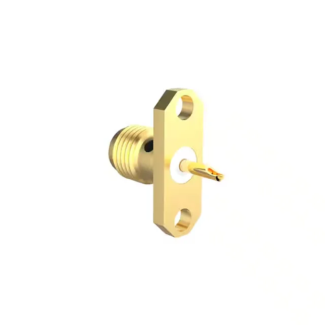
SMA Panel-Mount Jack for 18 GHz Signal Paths
The 901-5GF705590AE: The gold-plated stainless steel body and gold-over-beryllium copper centre contact deliver the corrosion resistance and mating-cycle life — 500 cycles — that field-service and repeated test connections demand.
What the 50 Ohm and 18 GHz Ratings Mean for Your RF Link
The 18 GHz frequency ceiling means the connector geometry is controlled to keep the VSWR low through the entire band. The PTFE dielectric is the usual choice here — stable dielectric constant across temperature and low loss up through these frequencies.
Extended Insulation — When the Creepage Path Matters
This variant carries an extended insulation feature, which means the dielectric protrudes further beyond the mating interface than a standard SMA. That extra creepage distance helps when the connector is used in higher-voltage or contaminated environments — think outdoor antenna mounts or industrial cabinets where condensation can bridge a standard interface. The trade-off is a slightly longer protrusion that may not fit flush with some panel cutouts; check the mechanical envelope against your enclosure before specifying.
Mounting and Termination — Flange, Solder, and the Panel Cutout
The connector mounts through a panel using the flange and is secured by the threaded coupling nut on the mating plug. The centre contact terminates via solder — a clean, low-resistance joint for the signal pin. The shield is also solder-terminated, which means the braid of a semi-rigid or flexible coax is soldered directly to the connector body. This is a permanent termination; no crimp tooling needed, but it does require a skilled hand with a soldering iron and heat management to avoid melting the PTFE dielectric.
The PTFE dielectric and beryllium copper contact maintain their mechanical and electrical properties across this span. For a connector that will see thermal shock or continuous high temperature, this is a solid envelope.