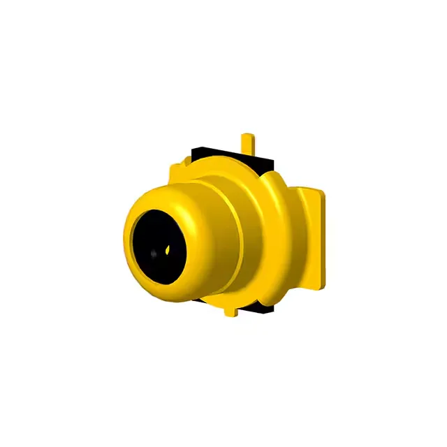
The gold-plated copper alloy body and center contact, along with the Liquid Crystal Polymer (LCP) dielectric, support signal integrity through the rated band. The push-pull fastening and full detent feature give a positive tactile mate and unmating without tools, suited for module-level interconnects or test points where the connector sees repeated connect/disconnect cycles.
The 2.5 GHz upper frequency limit defines the usable bandwidth; above that, the insertion loss and VSWR will climb. The 0.30 dB insertion loss at frequency is a typical figure for a Micro RF interface at this band, meaning the signal power loss through the connector is small enough that it doesn't require compensation in most link budgets.
Mating Cycles and Field Service Life
The gold-over-nickel center contact plating and gold body finish keep the contact surfaces clean and low-resistance through those cycles. The push-pull fastening with full detent gives a clear tactile click when fully seated, so the tech in the field knows the connection is made without needing a torque wrench.
Mounting and Termination for the Board Builder
The shield termination is solder, meaning the ground connection is made through the SMT pads on the PCB, not a separate ground leg. The LCP dielectric withstands reflow temperatures typical for lead-free soldering. Packaging options include Tape & Reel (TR) for automated pick-and-place lines, and Cut Tape (CT) for prototype or low-volume builds.
Operating Environment and Temperature Range
It is not rated for extended automotive under-hood or high-heat industrial processes above 85°C. The gold finish on the body provides corrosion resistance in mildly humid or indoor environments, but this is not an IP-sealed connector — it relies on the mated interface for environmental protection.
The 902-9040 is another Amphenol RF Micro RF jack in the same 902-92 base family, but it is a coaxial switch variant with a 4.30 mm plug diameter and snap-on fastening, versus the 902-9224's push-pull fastening. The choice between them comes down to frequency headroom versus mating cycle life: if your signal stays under 2.5 GHz and you need the higher reconnect durability, the 902-9224 is the fit; if you need to push to 6 GHz and can accept fewer mate cycles, look at the 902-9040.