Board Fit and Placement Considerations
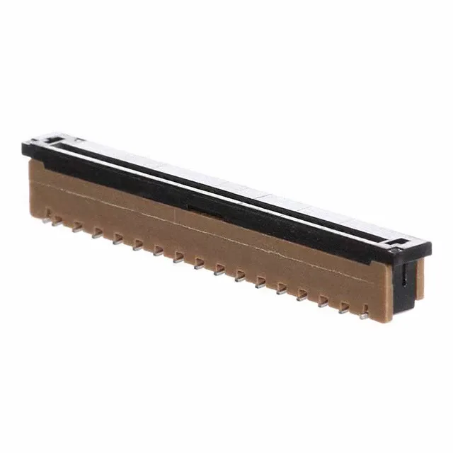
At this pitch, trace escape between pads is straightforward on a two-layer board, but impedance-controlled routing for high-speed signals may require a four-layer stack. The vertical orientation places the cable perpendicular to the board, which is useful when the cable exits upward into a panel or display. The SMD termination with no through-hole leads simplifies the assembly process and reduces board routing conflicts.
Molded-Closed Positions and Keying
Positions 5, 6, 7, 8, and 13 are molded closed, meaning the connector body blocks those contact cavities. This is a factory keying feature — it prevents insertion of a cable with conductors in those positions, which can be used to enforce a specific wiring pattern or to reserve those circuits for future use. A standard 30-conductor FPC with all conductors populated will not fully seat; the cable must have those positions left unpopulated or cut away.
Comparison with SFW30S-2STE1LF
The closest peer is the SFW30S-2STE1LF, which shares the same 30-position count, 1.00 mm pitch, 5.30 mm height, tin contacts, and ZIF feature. The key difference is the termination: the SFW30S-2STE1LF uses a kinked pin termination instead of the straight solder tail on the -2STME1LF variant. The kinked pin provides a mechanical interference fit in the PCB hole before soldering, which can improve alignment during reflow. For a BOM substitution, confirm that the footprint and solder paste stencil accommodate the kinked pin geometry.