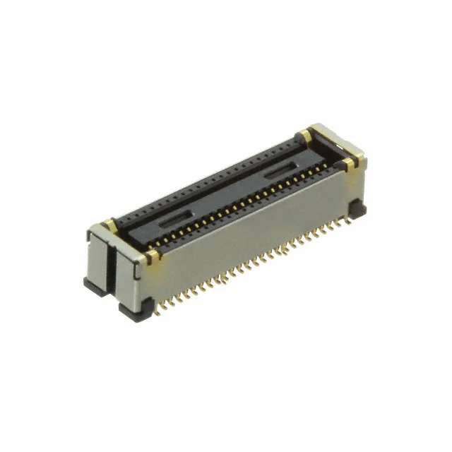
The Hirose DF40GB(3.0)-48DS-0.4V(58) is a 48-position receptacle from the DF40 series of board-to-board mezzanine connectors. The "(3.0)" in the part number indicates the mated stack height: 3 mm. The receptacle sits 0.114" (2.90mm) above the board surface, so the total z-height budget between the two PCBs is tight — 3 mm is a common gap in handheld devices, camera modules, and compact compute stacks where every tenth of a millimeter is allocated before layout starts.
At 0.40 mm pitch, the routing channel between pads is narrow — expect to use micro-vias and fine-line traces to escape the footprint. The 48 positions are arranged in two rows, so the connector body is long and narrow, not square. Compare this to the DF40GB(3.0)-70DS-0.4V(58), which carries 70 positions at the same 0.40 mm pitch and same 3 mm stack height — the footprint length scales with position count, so the board layout engineer picks by the number of signals that need to cross the mezzanine gap, not by connector family. Against the DF40GB(1.5)-48DS-0.4V(58) — same 48 positions and 0.40 mm pitch, but with a 1.5 mm mated stack height instead of 3 mm. The choice between the two is purely a z-height decision: 3 mm gives more room for component height on the underside of the top board, while 1.5 mm is for the tightest possible sandwich. The footprint is the same, so a board laid out for one can accept the other if the stack height changes.
Shielded Construction and Solder Retention
The shield is a metal shell that wraps around the contact area — it provides a continuous ground reference across the mated pair and reduces radiated emissions from the high-speed signals that typically run through a 48-position mezzanine. The solder retention features are extra metal tabs on the sides of the connector that solder to pads on the board, giving the joint mechanical strength against shear forces during handling and vibration. Without those retention tabs, a 48-position connector at 0.40 mm pitch would rely entirely on the signal-joint solder fillets to resist board flex — that is a reliability risk in portable equipment.