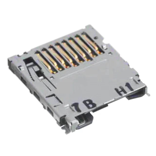
Board Layout Reality Check — This microSD Connector Mounts on the Bottom Edge
The Hirose DM3BT-DSF-PEJS is a reverse-mount, right-angle microSD™ card connector from the DM3 series. That "Reverse - Bottom" mounting feature means the card slot opens on the underside of the PCB — not the top — so the card inserts from the board edge and sits flush with the bottom surface. The connector stands 1.83mm above the board, which is the critical dimension for enclosure clearance: at that height, the card body stays within the board-to-case gap without forcing a thicker chassis. It handles 10 positions arranged as 8 data/control lines plus 2 dedicated card-detect switch contacts, and uses a push-push (push-in, push-out) ejection mechanism — the standard user action for a captive card slot.
Why the Reverse Mount Matters for Your Layout
Most microSD connectors mount on the top side of the board with the slot facing up. The DM3BT-DSF-PEJS flips that: the card loads from the bottom edge, which is useful when the PCB sits against an enclosure wall and the card needs to be accessible from the outside without a cutout in the top cover. The right-angle orientation means the card lies parallel to the PCB, not perpendicular — it slides in along the board plane, so the total z-height is just the connector body plus the card thickness. For a board-to-card stack, you need about 2.5mm of clearance below the PCB to accommodate the card and the ejection travel.
Position Count and the Switch Contacts
The 10 positions are split as 8 signal/control contacts and 2 switch contacts. The switch pair is the card-detect circuit: when a card is fully inserted, the switch closes (or opens, depending on the host circuit) to signal card presence.