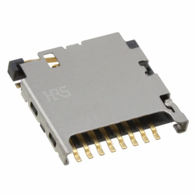
It carries 10 positions arranged as 8 data lines plus 2 dedicated switch contacts — the switch is built into the body to detect card insertion without a separate sensor. The connector sits 0.061" (1.55mm) above the board, which keeps the card slot low-profile for portable or embedded designs where z-height is tight. Gold plating on the contacts handles repeated card insertions without corrosion. The push-in, pull-out method means the card is held by friction and a light detent — no ejector mechanism, so the card stays put until you pull it.
The Switch Matters — Card Detection Built In
The integrated switch (listed as a Feature) is what separates this connector from a plain microSD header. When the card is fully seated, the switch contact closes — the host controller reads that signal to know a card is present before attempting to communicate on the data lines. That saves a dedicated detect pin elsewhere on the board. If your design already handles detection in software or through a separate GPIO, you could look at a connector without the switch, but for most embedded applications this is the cleaner path.
Board Fit and Assembly
That orientation works well for edge-of-board card slots in handheld devices, IoT modules, or single-board computers where the card needs to be accessible from the enclosure edge. The 1.55mm height above board is the dimension that matters for enclosure clearance: the card sits above that, so your case needs room for the card thickness plus the connector height. Gold contacts are standard for this class — they survive the 10,000+ insertion cycles a microSD slot sees over a product's life without the tin fretting that would cause intermittent contact on a cheaper finish.