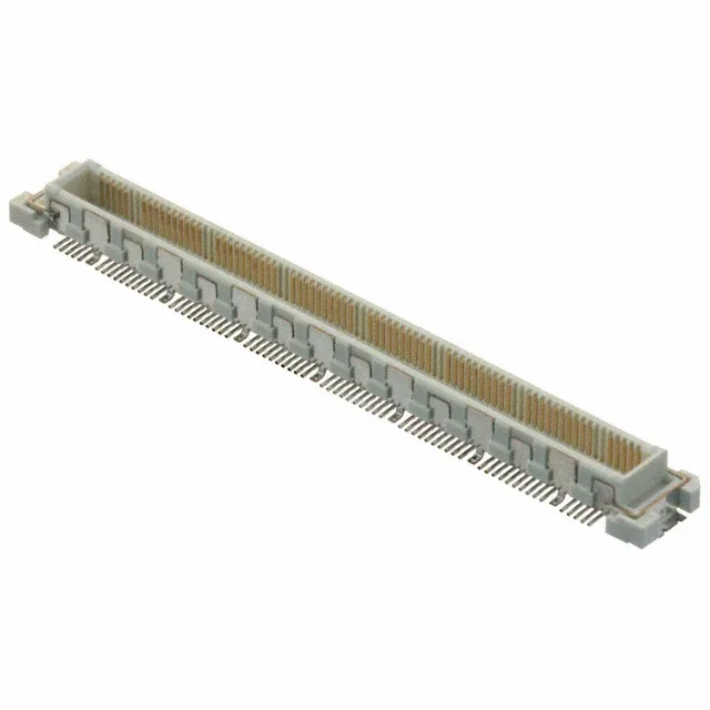
Hirose Electric Co Ltd FX10A-140P/14-SV(91) — Mezzanine & Stacking Connectors

Hirose FX10A-140P/14-SV(91) FunctionMax Header, 140 Pos

MPNFX10A-140P/14-SV(91)
Active

Hirose FunctionMax™ FX10 series, FX10A-140P/14-SV(91) header, outer shroud contacts, 140 positions, 2 rows, 0.020" (0.50mm) pitch, surface mount, gold contact finish 4.00µin, 4mm mated stacking height.

$7.5400Ref. price · indicative, final on quote
StockContact for availability
Lead timeIn Stock wk
MOQ1 pcs
  • New & original stockTraceable channels only — no mixed lots, no re-taped reels.
  • Factory packaging where availableSealed reels, trays and bags; cut quantities always stated on the quote.
  • Photo-verified countsEvery line counted and photographed before the box closes.
  • PayPal buyer protectionPay by T/T, PayPal or Payoneer — card payments covered end to end.

Specifications

FX10A-140P/14-SV(91) Technical Specifications
ParameterValue
SeriesFunctionMax™ FX10
MountingSurface Mount
Connector typeHeader, Outer Shroud Contacts
Height above board0.138\" (3.50mm)
Mated stacking heights4mm
Pitch0.020\" (0.50mm)
PackageTape & Reel (TR) Cut Tape (CT)
FeaturesBoard Guide, Ground Plate, Solder Retention
Contact finishGold
Rows2
Positions140
Contact finish thickness4.00µin (0.100µm)

Product details

What This 140-Position Header Does in a Board Stack

The Hirose FX10A-140P/14-SV(91) is a 140-circuit, 2-row header from the FunctionMax™ FX10 series, designed for parallel board-to-board stacking at a 4mm mated height. At a 0.50mm pitch, this is a dense signal interconnect — the 70 contacts per row require a careful PCB fan-out strategy to route traces between the pads. The outer shroud contacts provide mechanical protection during mating and help align the two boards before the pins engage. The board guide and ground plate are integrated features: the guide prevents pin stubbing during blind mating, and the ground plate provides a low-inductance return path that matters for high-speed signal integrity.

Stack Height and Footprint — the Two Dimensions That Decide Fit

The FX10A-140P/14-SV(91) uses a 0.138" (3.50mm) height above board, which means the mating receptacle sits 0.50mm above the header's mounting surface to reach the 4mm total. If your design needs a taller stack, the sibling FX10A-140P/14-SV1(91) delivers a 4.50mm mated height with a 0.177" (4.50mm) board standoff — same 140 positions, same 0.50mm pitch, same footprint, just a different z-height. The choice between them is purely a mechanical clearance decision. For a lower circuit count, the FX10A-120P/12-SV1(91) drops to 120 positions at the same 0.50mm pitch and 4.50mm stack height — useful when the BOM calls for fewer signals but the same board spacing and footprint pattern.

Surface Mount Assembly and Solder Retention

This is a surface-mount header — no through-hole tails, so the board requires no drilled vias for the signal pins. The Tape & Reel packaging (Cut Tape also available) feeds directly into a pick-and-place line, which is the standard assembly method for a 0.50mm-pitch part this dense.

Frequently asked questions

What is the mated stack height for FX10A-140P/14-SV(91)?

The mated stacking height is 4mm. The header itself stands 0.138" (3.50mm) above the board, so the mating receptacle contributes the remaining 0.50mm to reach the full stack height.

Will FX10A-140P/14-SV(91) drop into a board designed for FX10A-140P/14-SV1(91)?

The footprint and 140-position layout are identical between the two — same 0.50mm pitch, same 2-row arrangement, same outer shroud contacts. The difference is the stack height: 4mm for this part versus 4.50mm for the SV1 variant. If your enclosure and mating receptacle can accommodate the shorter gap, the board layout does not change.