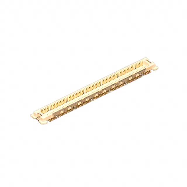
Hirose Electric Co Ltd FX11LA-120P/12-SV(92) — Mezzanine & Stacking Connectors

Hirose FX11LA-120P/12-SV(92) Header, 120 Pos, 0.50mm Pitch

MPNFX11LA-120P/12-SV(92)
Active

Hirose FX11 series header, outer shroud contacts, 120 positions, 2 rows, 0.020" (0.50mm) pitch, surface mount, gold plating 4.00µin, 1.90mm height above board, 2mm mated stack height.

$6.2500Ref. price · indicative, final on quote
StockContact for availability
Lead timeIn Stock wk
MOQ1 pcs
  • New & original stockTraceable channels only — no mixed lots, no re-taped reels.
  • Factory packaging where availableSealed reels, trays and bags; cut quantities always stated on the quote.
  • Photo-verified countsEvery line counted and photographed before the box closes.
  • PayPal buyer protectionPay by T/T, PayPal or Payoneer — card payments covered end to end.

Specifications

FX11LA-120P/12-SV(92) Technical Specifications
ParameterValue
SeriesFX11
MountingSurface Mount
Connector typeHeader, Outer Shroud Contacts
Height above board0.075\" (1.90mm)
Mated stacking heights2mm
Pitch0.020\" (0.50mm)
PackageTape & Reel (TR) Cut Tape (CT)
FeaturesBoard Guide, Ground Plate, Solder Retention
Contact finishGold
Rows2
Positions120
Contact finish thickness4.00µin (0.100µm)

Product details

The Hirose FX11LA-120P/12-SV(92) is a 120-position header from the FX11 series, designed as a board-to-board mezzanine interconnect. It uses a 0.50mm pitch and a 2mm mated stack height, placing it in the high-density, low-profile segment of parallel board stacking. The outer shroud contacts with gold plating at 4.00µin suit signal-level duty where repeated mating cycles are moderate — think portable electronics, handheld instruments, or any assembly where board spacing is tight and position count is high. The ground plate and board guide features help align the connector during SMT placement and provide a low-impedance return path, which matters for signal integrity in dense digital designs.

Board Layout and Assembly Considerations

The 1.90mm height above board is the standoff after soldering — the mating receptacle sits on the opposing board at the same height, giving a total 2mm stack between PCBs. The board guide eases alignment during manual or automated mating, and the ground plate ties to the board ground plane through multiple solder tabs, which helps control EMI in high-speed designs. The 0.50mm pitch demands careful PCB layout — trace routing between pads is tight, and a four-layer board with buried vias is typical for fanning out 120 signals.

The closest sibling in the FX11 series is the FX11LA-100P/10-SV(92), which shares the same 0.50mm pitch, 1.90mm height above board, and 2mm stack height but carries 100 positions instead of 120. The 140-position variant FX11LA-140P-SV(22) exists for even higher density, but note it lacks the ground plate feature present on the 120- and 100-position versions, which may matter for EMI performance.

Frequently asked questions

What is the recommended PCB layout for FX11LA-120P/12-SV(92)?

The 0.50mm pitch and 120 positions on two rows require a tight SMD footprint matching the Hirose product drawing. The board guide and ground plate solder tabs need corresponding pads and ground-plane vias. A four-layer PCB with micro-vias or buried vias is typical for routing all 120 traces out from under the connector.