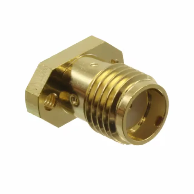
Hirose Electric Co Ltd HRM(G)-300-468B-1 — RF Cable Assemblies

Hirose HRM(G)-300-468B-1 SMA Jack, 50 Ohm, 28 GHz

MPNHRM(G)-300-468B-1
Active

Hirose HRM(G) series SMA jack, female socket, 1 port, 50 Ohm, DC to 28 GHz, panel mount with flange, threaded fastening, gold-plated brass body, solder contact termination, 500 mating cycles.

$12.0200Ref. price · indicative, final on quote
StockIn Stock (19)
Lead timeIn Stock wk
MOQ1 pcs
  • New & original stockTraceable channels only — no mixed lots, no re-taped reels.
  • Factory packaging where availableSealed reels, trays and bags; cut quantities always stated on the quote.
  • Photo-verified countsEvery line counted and photographed before the box closes.
  • PayPal buyer protectionPay by T/T, PayPal or Payoneer — card payments covered end to end.

Specifications

HRM(G)-300-468B-1 Technical Specifications
ParameterValue
SeriesHRM(G)
MountingPanel Mount
Connector typeJack, Female Socket
Fastening typeThreaded
Frequency - max28 GHz
Mounting featureFlange
Operating temperature-55°C~85°C
Body materialBrass
Housing colorGold
Dielectric materialPolytetrafluoroethylene (PTFE)
Center contact materialBeryllium Copper
PackageBulk
FeaturesMounting Hardware
Impedance50Ohm
Body finishGold
Mating cycles500
Number of ports1
Shield terminationScrew
Contact terminationSolder
Center contact platingGold

Product details

SMA Panel Jack for DC-28 GHz Signal Paths

The HRM(G)-300-468B-1: It carries a single port with a gold-plated brass body and a PTFE dielectric, rated from DC up to 28 GHz. The threaded fastening and flange mounting feature let you secure it to a panel face with the mating half torqued to a repeatable interface — standard practice for test equipment, instrumentation, and microwave assemblies where the connection sees repeated mate-unmate cycles.

What the 28 GHz and 500 Mating Cycles Mean on the Bench

The 28 GHz maximum frequency covers Ku-band and K-band signals with headroom, making it a fit for satellite communications, radar front-ends, and high-speed digital test.

Mounting and Termination — Panel Fit and Solder Tail

The connector mounts through a panel hole with the flange sitting flush against the outside face; the four screw holes in the flange take #4 or M2.5 hardware (not included) to hold the body rigid against the panel. Shield termination is via a screw — a separate ground lug or braid ring clamps to the body, not through a solder tab. The centre contact terminates with a solder cup: strip the coax centre conductor, tin it, and flow solder into the cup. The PTFE dielectric supports the centre pin and keeps the impedance stable through the transition from cable to connector body.

Frequently asked questions

What is the impedance of HRM(G)-300-468B-1?

The impedance is 50 Ohm, the standard for RF and microwave transmission lines. This matches the characteristic impedance of common coaxial cables like RG-316, RG-142, and semi-rigid.085" or.141" types.

What is the frequency range of HRM(G)-300-468B-1?

It is rated from DC to 28 GHz, covering L-band through K-band. The PTFE dielectric and gold-plated beryllium copper centre contact maintain consistent impedance across that band.