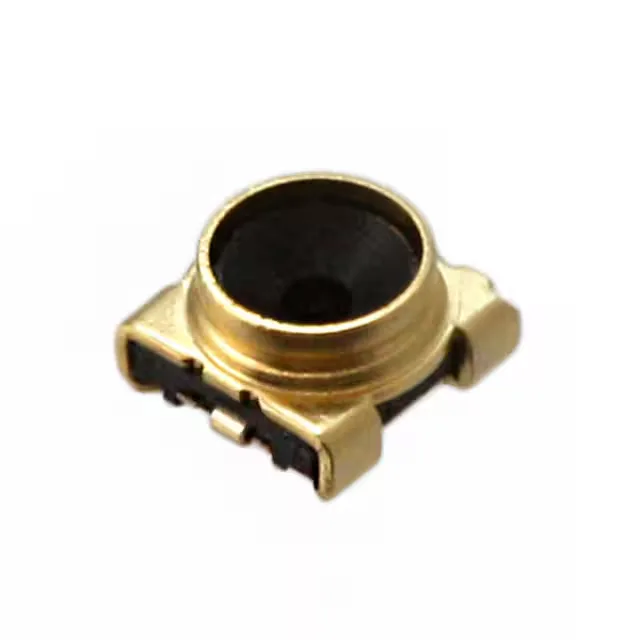
Coaxial Switch Receptacle for 11 GHz Signal Paths
The Hirose MS-156C3(20) is a 50 Ohm coaxial switch receptacle from the MS-156C series, designed for RF signal routing up to 11 GHz. The internal switch feature lets the connector select between two signal routes without an external relay — useful in antenna diversity circuits, test equipment, and module-level RF switching. The gold body finish and gold-plated center contact (copper alloy) keep contact resistance low and resist corrosion over the rated 100 mating cycles. The SMT mounting and solder shield termination suit automated assembly on RF PCBs where controlled impedance is critical.
What the 11 GHz and 0.4 dB Specs Mean for Your RF Design
The 11 GHz max frequency and 0.4 dB insertion loss are the two specs that define this connector's signal-integrity envelope. At 11 GHz, the insertion loss of 0.4 dB means the signal loses less than 10% of its power through the switch — tight enough for most receiver front-ends and test paths. For a board layout engineer: the SMT footprint must match the recommended land pattern to keep the impedance discontinuity below the connector's own 0.4 dB budget.
Mating and Termination — Snap-On, SMT, Solder Shield
The fastening type is snap-on — the mating plug pushes onto the receptacle and locks with a detent, no threads or bayonet. The 100 mating cycles are enough for field-swappable modules and test fixtures but not for daily reconnect in a production test handler. The contact termination is also solder — the center pin solders to the PCB trace. The single-port design means one signal path in, one switched path out (or through). The internal switch is normally closed to one position and opens when the plug is inserted, routing the signal to the plug path.