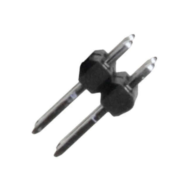
Board Layout Fit – Pitch, Rows, and Footprint
The 0010897041: The row spacing is also 0.100" (2.54mm), so the overall footprint is a standard 2×2 pin array that fits prototyping boards and legacy through-hole layouts. No shroud guides the plug, so the board-level keep-out zone is minimal, but the mating pair relies on the housing keying of the receptacle. Contact length – mating is 0.240" (6.10mm), post length is 0.107" (2.71mm), overall length 0.437" (11.10mm). The post length is short enough for single-sided boards; double-sided or thicker boards may need a longer post variant from the same series.
Mating and Termination – What Connects Here
The male pin header mates with C-Grid 70280 series crimp receptacle housings (e.g., Molex 70066 series) or with IDC socket connectors from the same C-Grid family. The push-pull retention relies on the receptacle's latch – no secondary locking on the header side. No press-fit or SMT option on this variant; the board must have plated through-holes on a 0.100" grid. That thickness is well above flash tin – it supports repeated mating cycles without galling or exposing the base metal, which matters for test points or field-service connections.
No additional environmental compliance restrictions beyond standard commercial use.
Application Range – Where This Header Goes
Listed applications include Automotive, General Purpose, Lighting, Medical, and Telecommunications. The UL94 V-0 housing and tin plating suit low-to-moderate current signal paths in these environments – the header itself is unsealed, so the system's IP rating depends on the mating receptacle and enclosure. Style is Board to Board or Cable. The unshrouded header can connect two PCBs via a mezzanine socket, or terminate a cable harness through a crimp receptacle. The dual-row 4-position layout is common for sensor power/signal or small I/O breakouts.