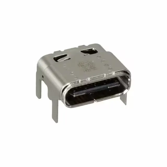
It carries the USB 3.2 Gen 2 specification — that is 10 Gbps data rate, also known as Superspeed+ — making it a full-featured USB-C port for modern high-speed interfaces. The 24 contacts handle the full USB-C signal set including the configuration channel (CC) and sideband use (SBU) pins required for alternate modes like DisplayPort over USB-C. This is a receptacle (the board-side half), not a plug.
The current rating is split across three values — 0.25 A, 1.25 A, and 5 A — because USB-C uses multiple power rails. The 5 A path is for the VBUS power delivery pins (the main power rail), the 1.25 A is typical for the configuration channel and sideband pins, and the 0.25 A covers the signal contacts. This is not a single derating curve; each contact group has its own limit based on pin count and duty in the USB-C spec. For a 5 A power delivery application, the connector itself is rated for it, but the PCB trace width and the cable gauge must match that current. The 30 V rating is the maximum voltage the connector is designed to withstand across any pin combination. 20,000 mating cycles is an order of magnitude above a typical consumer USB-C connector (usually 10,000). That cycle life points to a reinforced contact beam design, likely for equipment that sees frequent plugging — test fixtures, public kiosks, industrial handhelds, or docking stations. The gold contact finish supports that cycle count without fretting corrosion. The shielded construction with a steel and stainless steel shell provides a continuous ground reference around the signal pins.
The connector is surface-mount right-angle (SMD RA) for the signal pins, with additional through-hole anchor posts for mechanical retention. The SMD pads handle the electrical connection; the through-hole posts take the shear force from cable insertion and extraction, preventing the solder joints from cracking. The black insulation color is standard for USB-C receptacles and provides visual contrast for automated optical inspection of the solder joints.