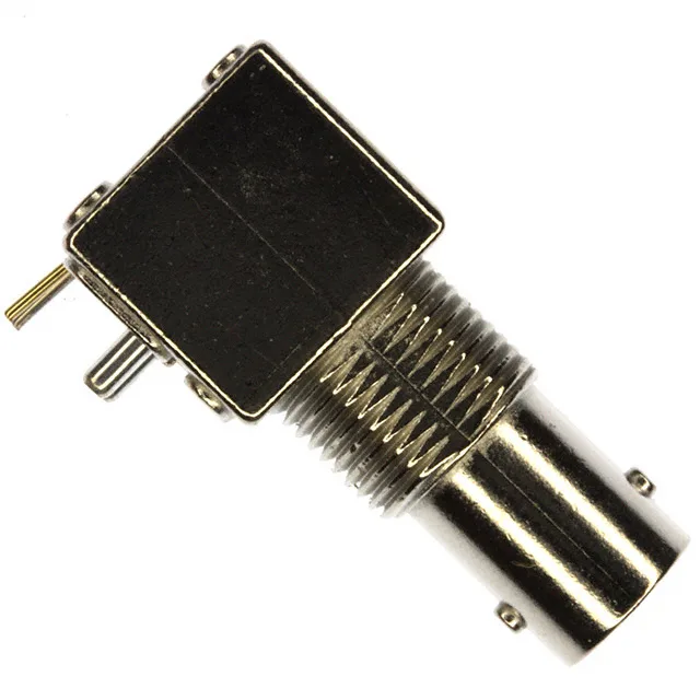
The 1-1634508-0: Rated to 2 GHz maximum frequency, this jack handles standard-definition analog video, HD-SDI digital video up to 3G-SDI rates, and baseband surveillance camera feeds without rolling off the signal edges. The centre contact is gold-plated brass, which keeps contact resistance low and resists corrosion through the rated 500 mating cycles. The body is nickel-plated zinc alloy — the nickel finish provides a durable, corrosion-resistant shell for the bulkhead mount, and the zinc alloy casting gives the bayonet locking mechanism a solid feel when mated. The fastening type is bayonet lock — a quarter-turn twist engages the mating plug's pins into the jack's J-slots, giving a positive mechanical connection that resists vibration better than a friction-fit BNC.
Panel Mount with Right-Angle PCB Termination
The mounting arrangement is a bulkhead — front side nut — meaning the jack inserts from the outside of the panel and a nut tightens from the inside to clamp it in place. This is the standard method for a fixed panel-mount BNC: the connector body becomes the panel jack, and the bayonet interface is accessible from the front. The right-angle through-hole solder tails extend from the rear of the connector body, so the PCB mounts parallel to the panel face. Shield termination is solder — the braid or foil of the coaxial cable is soldered directly to the connector body or to a solder cup on the shield termination feature. This gives a solid, low-impedance ground path for the shield current at RF frequencies. The contact termination is also solder, so the centre conductor is soldered to the centre pin. Both terminations are manual operations — no crimp tooling required, but the solder joints need to be clean and consistent for the 75 Ohm impedance to hold through the transition.
Obsolete — Sourced Through Surplus and Broker Channels
The 1-1634508-0 is marked Obsolete in the TE Connectivity lifecycle system. No official successor part number is listed in the available records.
If your system is built around 50 Ohm coaxial cable (RG-58, RG-213, LMR-400) or 50 Ohm test equipment, this jack will create an impedance mismatch at the connection point — the reflected energy shows up as a ripple in the passband and a roll-off in the time-domain response. Stick with 50 Ohm BNC parts for RF test, telecom, and wireless infrastructure. For video, broadcast, and surveillance systems that already use 75 Ohm cable and terminations, this jack is the correct match. The 2 GHz maximum frequency is a practical ceiling for this connector. At frequencies above 2 GHz, the mechanical tolerances of the BNC bayonet interface and the dielectric material start to introduce mode conversion and return loss degradation. For standard-definition analog video (below 10 MHz) and HD-SDI digital video (1.485 Gbps, fundamental frequency around 750 MHz), the 2 GHz rating provides healthy margin. For 3G-SDI (2.97 Gbps, fundamental around 1.5 GHz), the connector is still within its rated band but the return loss at the upper end should be verified against the system budget. After 500 cycles, the contact wear may increase resistance and the bayonet lock may feel loose. For a fixed installation that is mated once and left, the cycle life is irrelevant; for a production test fixture cycling daily, 500 cycles is a few months of operation.