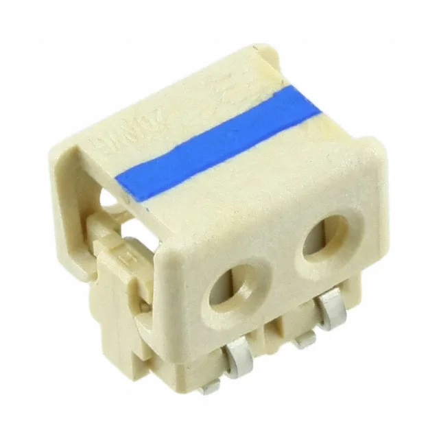
It sits on a 0.157" (4.00 mm) cable pitch, matching the same 0.157" (4.00 mm) board-side pitch, so the wire spacing and the PCB footprint align one-to-one. The housing is natural-colour, single-row, with all positions loaded. The Feed Through feature means the IDC slot passes the wire through the connector body — the wire exits the far side, which can simplify daisy-chain wiring or pass-through routing in a harness. This connector is built for board-level interconnect of discrete wires — think LED strip power taps, sensor leads, or low-current control wiring inside an enclosure where a ribbon cable or discrete harness needs a clean SMD termination. The 20 AWG wire gauge handles moderate current; the actual ampacity depends on the wire insulation rating and ambient temperature, but the IDC contact itself is rated for the wire's full current capacity within the connector's temperature range.
The 0.157" (4.00 mm) pitch is wider than the common 0.100" (2.54 mm) IDC pitch, which means the PCB footprint is more forgiving for routing traces between pads — you can run a 20-mil trace between two pads without necking down. The trade-off is that the connector body is physically larger per position, so a 2-position part like this one still occupies about 0.31" of board edge. For a 2-circuit BOM line, the pitch is not a density concern; it is a footprint-matching check against the existing board layout.
IDC Termination — Assembly Note
The IDC termination accepts 20 AWG solid or stranded wire. The wire is laid into the slot and pressed down with a hand tool or pneumatic press — the slot's insulation-displacing blades cut through the insulation and grip the conductor. No solder, no crimp barrel, no wire prep beyond cutting the wire to length. The Feed Through feature means the wire exits the far side of the connector, so you can daisy-chain the same wire to a second connector if the harness topology calls for it.