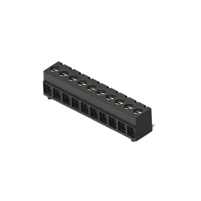
It terminates wires with a screw-driven rising cage clamp — the screw tightens a clamp that pushes the wire against the current bar, giving a gas-tight connection without wire preparation beyond stripping. The 3.81 mm pitch provides enough spacing for the 300 V rating and makes board layout straightforward even with 16 AWG wire. The surface-mount termination is the distinguishing feature here: this block is designed for reflow soldering, not hand-soldering into plated through-holes. Typical applications include industrial control I/O modules, building automation controllers, and power distribution boards where a compact, automated assembly process is needed.
Sizing the Wire and Setting the Torque
The rising cage clamp accepts 16 to 28 AWG solid or stranded wire. The screw is M2 thread, and the specified torque range is 0.5-0.6 Nm (4.4-5.3 Lb-In) — a calibrated screwdriver is needed to avoid stripping the threads or under-clamping the wire. The clamp and screw are both copper alloy with nickel plating, which resists corrosion in humid cabinet environments. The contact itself is copper alloy with nickel-tin plating, a good match for the 12 A rating without excessive heating.
This is a surface-mount device, so the board footprint must match the 3.81 mm pitch and the block's solder pad layout — no through-hole holes to align. The mating orientation is horizontal with the board, meaning the wire entry is parallel to the PCB surface. A board guide feature on the housing helps align the part during pick-and-place.