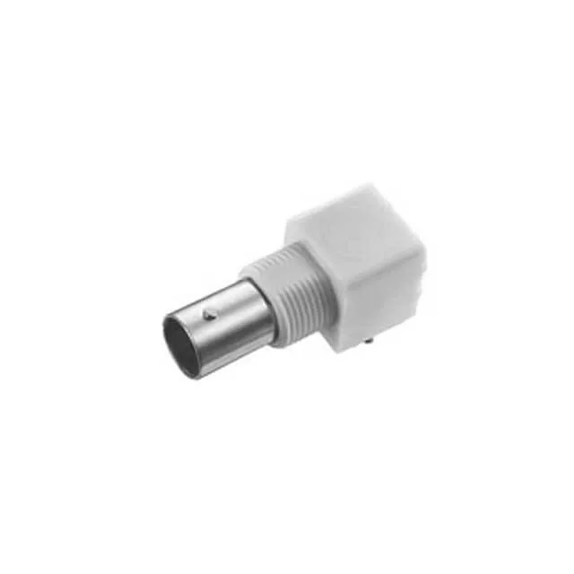
The 1-5227161-6: It's a bulkhead-mount design with a right-angle PCB solder tail, which means the signal path turns 90 degrees at the board edge rather than running straight through the panel. That matters when the PCB sits parallel to the panel face and you need to keep the RF trace short to the connector launch.
The right-angle panel mount — why that combination is unusual
Most BNC jacks are either straight panel-mount (the signal axis runs through the panel) or right-angle PCB-mount without a panel flange. This one does both: it bolts to the panel via a front-side nut through a bulkhead hole, and the centre contact and shield terminate to the PCB through right-angle solder posts. The board guide and isolated features suggest the PCB sits in a defined slot or chassis, and the connector body is electrically isolated from the panel ground — you'd run a separate ground bond rather than relying on the shell-to-chassis contact. The shield termination is solder, not a crimp ferrule, so the braid or ground trace ties directly to the board.
Above 4 GHz the return loss climbs and the VSWR specification is no longer guaranteed; for 6 GHz work you'd step to a BNC rated to 6 or 12 GHz, or move to an N-type or SMA. The 500 mating cycles are standard for a BNC bayonet-lock interface: the coupling nut wears, not the centre contact, so the cycle life is limited by the plating on the bayonet slots rather than the signal pin.