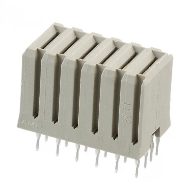
Backplane Power Blade Receptacle for Solderless Assembly
It accepts female blade sockets and terminates via press-fit into a plated through-hole board, eliminating the need for a wave solder step in high-reliability backplane builds. The single-row layout with all 6 positions loaded as power contacts makes it a compact solution for distributing bus-level voltage across a backplane midplane or power distribution board.
Press-Fit Termination and Board Layout Fit
The interference fit creates a cold-weld joint that is more resistant to vibration and thermal shock than a soldered connection. For the board layout engineer, this means the PCB must be specified with the correct finished hole size and plating thickness per the TE application specification — the hole tolerance is tighter than for a solder-tail part, and the board stack-up must allow the press-fit pin to bottom out without stressing the backplane laminate. The 6 positions in a single row keep the board footprint narrow, which is useful when routing power traces on a dense backplane. Because the connector is a receptacle, the mating blade header (the male half) plugs into it from the opposite side of the board or from a daughtercard, depending on the backplane architecture. The press-fit pin length and the board thickness must be matched — typical backplane thicknesses for this series range from 2.36 mm to 3.18 mm, though the exact stack-up should be verified against the TE product drawing.
Mating Half and System Integration
The blade power contact layout — 6 power positions — means the mating header will have 6 blade terminals that insert into the female sockets of this receptacle.