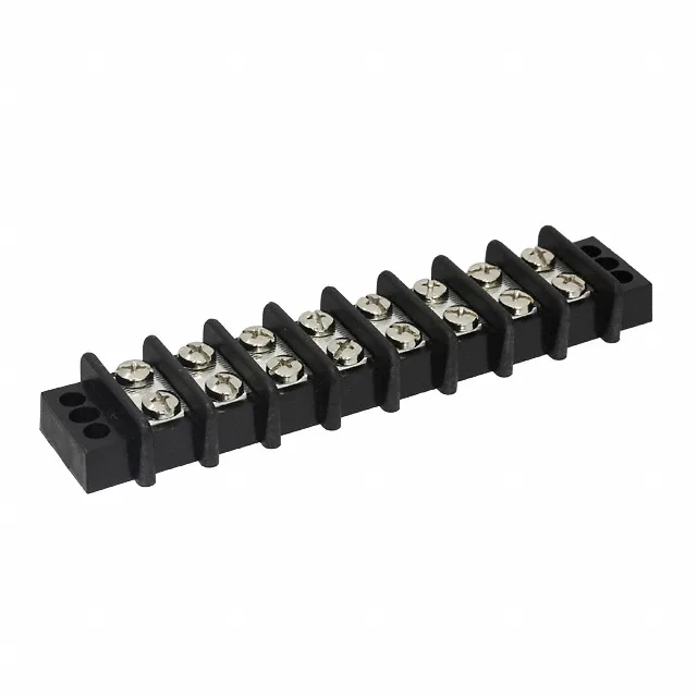
Panel-Mount Barrier Block, 8 Circuits, 30 A per Position
The 1546310-8: It accepts 10-22 AWG wire and terminates via screws on top with a closed bottom — meaning the screw clamps down on the wire against a solid barrier, no feed-through. The dual-wall (2 Wall) barrier design provides isolation between adjacent terminals, reducing the chance of accidental shorting during wiring. The flange on each end allows panel mounting with screws, securing the block to a chassis or enclosure wall.
Wire Gauge and Termination — 10-22 AWG, Screw Clamp
The 1546310-8 accepts wire from 10 AWG down to 22 AWG — a wide range that covers most power distribution and control wiring. The top termination uses steel screws with a nickel finish; the screw head bears directly on the conductor. The closed bottom means the wire is captured between the screw and the insulator base, not passed through to the other side. For a 30 A circuit, 10 AWG is the practical minimum for full-rated current over any distance; 22 AWG is fine for signal-level taps. The 16 wire entries (8 circuits × 2 rows) allow daisy-chaining or dual-wire termination per position.
This barrier block is designed for chassis or panel mounting — the integral flange accepts a screw on each end to secure it. The 300 V rating is typical for control circuits and secondary power distribution within a panel.
It is ROHS3 Compliant.