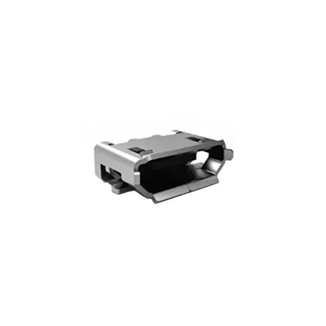
What This Micro-B Receptacle Delivers
Gold plating on the contacts handles the 10,000 mating cycles — that figure is well above the 5,000–6,000 cycles typical for a consumer-grade micro-B, so this part is sized for field-serviceable equipment or test-fixture ports where the cable gets plugged and unplugged regularly.
Current Rating — What the Three Values Mean
The spec table lists current ratings of 0.5A, 1A, and 1.8A. This is not a range — it reflects the USB 2.0 power delivery hierarchy: 0.5A is the standard USB 2.0 low-power port limit, 1A covers a typical charging port, and 1.8A is the maximum per-contact rating before the temperature rise hits the 85°C operating ceiling of the housing. For a BOM line, the relevant figure depends on the host controller's power profile; the connector itself can handle the full 1.8A on the VBUS contact as long as the board layout provides adequate copper for heat spreading.
This is a surface-mount right-angle receptacle, so the PCB footprint needs the standard micro-B SMT pad layout with the two SMT anchor tabs for shear retention. The 30V rating covers the VBUS line at any USB 2.0 power level. The mating half is any standard USB micro-B plug — the 5-contact pinout follows the USB 2.0 assignment: VBUS, D−, D+, ID, and GND. There is no board lock or through-hole anchor; the SMT solder joints alone carry the insertion and extraction forces, which is standard for this connector class.