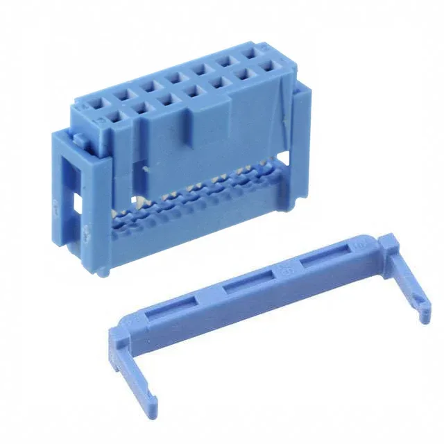
IDC Receptacle for 0.100" Ribbon Cable — 14-Position, Gold Contacts
The TE Connectivity 2-1658527-2 is a 14-position, 2-row receptacle from the 622 series, terminated via IDC to 26-28 AWG stranded or solid ribbon cable. The 0.100" (2.54mm) pitch on both rows and between rows matches the standard grid of 0.025" square post headers — the de facto footprint for parallel data and control interfaces. The housing includes a polarizing key to prevent mis-mating and an integral strain relief that clamps the cable jacket behind the IDC slots — without it, the termination relies entirely on the insulation grip of the slot itself. Free-hanging (in-line) mounting, blue housing, bulk packaging.
Pitch and Footprint — 0.100" Grid Standard
The 0.100" (2.54mm) pitch on both the contact row and the row-to-row spacing means this receptacle mates directly with any standard 0.100" pitch header.
Termination and Wire Range — IDC for Ribbon Cable
IDC termination punches through the insulation of 26-28 AWG stranded or solid ribbon cable in one press operation — no individual wire stripping or crimping. The 622 series IDC slot geometry is designed for ribbon cable with a standard 0.050" conductor spacing, which is the most common pitch for 28 AWG rainbow ribbon. The integral strain relief clamps the cable jacket behind the termination point, transferring pull loads to the housing rather than the IDC slots. For field replacement, the same connector can be re-terminated onto a new cable section, though the gold contacts are rated for multiple insertion cycles into the header, not repeated IDC re-termination.
Mating and Locking — Polarized, No Secondary Latch
This receptacle mates with any 0.100" pitch 2-row header that has 14 positions — typically a TE 1-826629-4 or equivalent breakaway header. The polarizing key in the housing (a molded rib on one side) prevents backward insertion onto the header, which would reverse the signal mapping. In high-vibration environments, an external strain relief clamp or cable tie is advisable to prevent the connector from walking off the header. The feed-through feature (open top) allows daisy-chaining multiple connectors on the same ribbon cable — the IDC slots pass the signal through to the next connector in the chain.
Contact Plating — 30.0µin Gold for Field Duty
The 30.0µin (0.76µm) gold plating on the female socket contacts is the standard thickness for applications requiring 50-100 mating cycles — typical for test equipment, programming jigs, or field-replaceable cable assemblies. Tin-plated contacts would gall and degrade after 10-20 cycles at this pitch; the gold layer prevents oxide buildup and maintains consistent contact resistance below 20 mOhm through the life of the connection. The gold is over a nickel barrier, which prevents copper migration from the base alloy. For a one-time install inside an enclosure that is never opened, tin contacts would suffice — the gold here signals that the designer expects the cable to be disconnected and reconnected multiple times.
No official second-source cross-reference exists; the 1-226733-4 is a 17-position variant in the same 622 series but does not match the 14-position count. If the BOM calls for exactly 14 circuits, this is the direct line item.