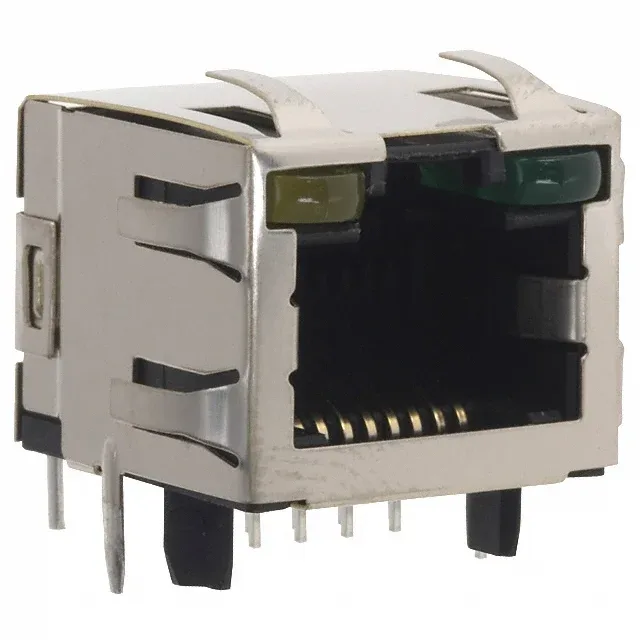
It carries a Cat5 rating, meaning it's specified for 100 MHz signaling in 10/100BASE-T Ethernet applications.
Shielding, LED, and the Cat5 Rating
The shielded construction with EMI finger provides a chassis ground path that keeps the connector's radiated emissions under control — essential for passing FCC/EN 55032 in equipment with a metal panel. The yellow-green LED is built into the jack body, so you don't need a separate indicator on the board for link/activity status; it's driven by the PHY's LED outputs. The Cat5 rating limits the connector to 100 MHz, which covers 10BASE-T and 100BASE-TX but not 1000BASE-T (Gigabit Ethernet) — if your design needs Cat5e or Cat6, this jack isn't the match.
Board Layout and Orientation
It's a through-hole solder termination — the 8 signal pins and two shield ground pins anchor into plated through-holes, giving better shear strength than an SMT version would offer.