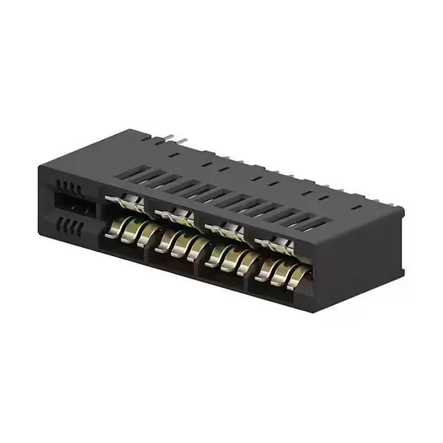
16-Position Dual-Readout Edge Connector for Press-Fit Backplanes
It accepts a non-specified dual-edge card with a thickness of 0.055" (1.40mm) and arranges its 16 contacts across two rows in a dual-readout configuration — meaning each card-edge pad is contacted on both sides, doubling the signal density per slot compared to a single-readout design.
Why Press-Fit Matters for This Connector
In a backplane or midplane assembly, this eliminates the thermal cycle of wave soldering, avoids solder-joint defects like voids or bridging, and makes the connector field-reworkable — a failed pin can be staked out and replaced without desoldering. The trade-off is a tighter PCB hole tolerance: the finished hole diameter must match the press-fit pin geometry per the application drawing, or the retention force drops.
Gold resists corrosion and maintains stable contact resistance through multiple insertions — a 30 µin layer typically supports several hundred cycles before wear-through to the nickel underplate. For a fixed backplane that mates only during initial assembly and occasional field service, this is generous margin; for a hot-swap drawer that cycles weekly, it is the right starting point.
This connector mates with a non-specified dual-edge card — essentially a bare PCB edge with gold fingers on both sides, 0.055" (1.40mm) thick. There is no keying or polarisation feature in the slot; the card edge must align with the connector's dual-readout contacts. On the solder side, the press-fit tails go into a through-hole pattern that matches the MULTI-BEAM CE footprint.