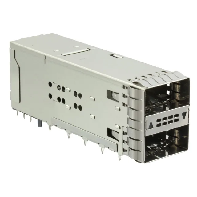
What this ZQSFP+ receptacle does on the board
It carries 76 positions arranged as 38 per port. The press-fit termination pushes through plated holes in the PCB, no solder wave needed, which keeps the assembly compatible with reflow-only boards and avoids the thermal stress of wave soldering on the backplane. EMI shielding is integrated into the cage, and the light pipe channels port-status LEDs to the front bezel without a separate light guide assembly.
Press-fit means the compliant pin compresses into the plated through-hole and cold-welds to the barrel — no solder joint, no void inspection, no hand-solder rework. The through-hole right-angle mounting gives the cage mechanical support against the insertion force of a QSFP+ / ZQSFP+ module. The board footprint needs plated holes sized for the press-fit pin diameter; the recommended hole finish is in the TE application drawing. Light pipe output sits at the cage face — the PCB layout must align the LED driver to the light pipe input. The tray package delivers the connector in a single rigid tray, which protects the press-fit pins from bending during handling.