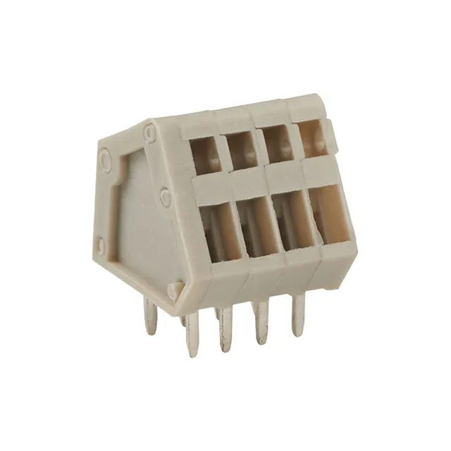
What This 2-Position Terminal Block Does on Your PCB
The 0.098" (2.50mm) pitch keeps the board footprint compact — each circuit occupies just 2.5 mm of board edge, so a 2-position block takes up about 5 mm plus the side interlock tabs. Rated 4 A per circuit at 150 V, it handles low-power sensor feeds, signal wiring, or control loops where you need a reliable gas-tight connection without a screwdriver. The 45° (135°) wire entry angles the conductor relative to the PCB, which helps in enclosures where vertical space above the board is tight.
Wiring It: Spring Cage vs. Screw Clamp
The spring cage termination is the key differentiator here. You push the stripped wire into the clamp opening — the spring applies constant force on the conductor, creating a gas-tight joint that resists thermal cycling and vibration better than a screw terminal that can back out over time. No screwdriver needed, which speeds up panel wiring when you're landing a dozen of these on a board. The 20-28 AWG range covers most signal and small power wires; for 20 AWG, make sure the strip length matches the clamp depth per the manufacturer's drawing. The side interlocking feature lets you snap multiple 2-position blocks together to form a larger multi-position assembly — 4, 6, 8 positions, and so on — without buying a single wider terminal block. The interlock tabs on the housing side walls key into the adjacent block, so the assembly stays aligned on the PCB. This is useful when your BOM calls for a non-standard position count or when you want to stock one base part for several circuit counts.
Board Layout and Orientation
Through-hole mounting gives the block mechanical strength on the PCB — the pins solder into plated holes and take the insertion force of the wire without stressing the solder joints. The 45° wire entry means the wires exit at an angle to the board surface, not straight up. In a shallow enclosure, this can save 5-10 mm of vertical clearance compared to a vertical-entry block.