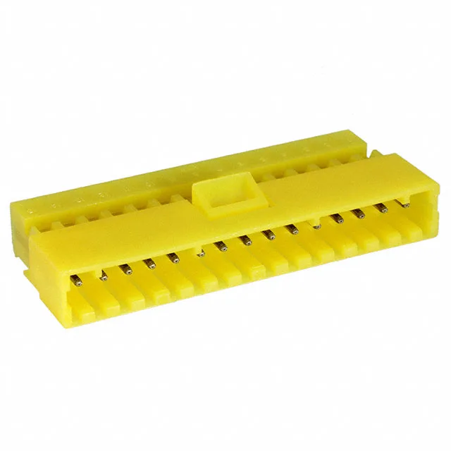
MTA-156 IDC Plug, 15 Circuits, 20 AWG — Yellow Housing for Harness ID
The 0.156" (3.96mm) pitch matches the standard MTA-156 header footprint, and the yellow closed-end housing provides both wire stop and visual circuit identification in multi-wire harnesses.
What the 0.156" Pitch and 15 Positions Mean for Your Board Fit
The 0.156" (3.96mm) pitch is the defining dimension for board layout — it matches the standard MTA-156 through-hole header footprint, giving 3.96mm center-to-center spacing between adjacent pins. The 15 positions must match the circuit count on your BOM and the mating header exactly; this plug mates with any 15-position MTA-156 vertical or right-angle header (male pin receptacle). The single-row layout keeps the connector width to 15 × 0.156" = 2.34" plus housing overhang, which fits standard 0.156" pitch board patterns.
IDC Termination — Fixed 20 AWG, No Stripping Required
This plug uses insulation displacement contacts (IDC) sized specifically for 20 AWG wire — the slot width and insulation pierce geometry are fixed for that gauge. You load the wire into the slot and press down with a hand tool or press; the contact displaces the insulation and grips the conductor without stripping or crimping individual terminals. The closed end acts as a wire stop, preventing the conductor from pushing through the back of the housing. For ribbon cable, the IDC slot aligns with standard 0.156" pitch ribbon; for discrete wires, each position terminates independently.
Free-Hanging Right-Angle Mount — Cable Exit Parallel to Board
The free-hanging (in-line) right-angle orientation means the cable exits at 90° to the plug face, running parallel to the PCB when mated with a vertical header. This is useful in enclosures where the cable must route along the board surface rather than standing straight up. The plug has no mounting ears — it relies on the header's latch or friction retention to stay mated. For vibration-prone environments, consider adding a secondary strain relief or tie-down point on the cable bundle.
Tin Plating at 80 µinch — Signal Duty, Not High-Cycle Power
The 80.0µin (2.03µm) tin contact finish is a thick tin layer suitable for moderate mating cycles (typically 25-50 cycles) in signal and low-current applications. Tin is cost-effective and provides good corrosion resistance in indoor environments, but it does not match the cycle life of gold-plated contacts (which handle 500+ cycles). For applications requiring frequent disconnect/reconnect or exposure to corrosive atmospheres, consider the gold-plated variant in the MTA-156 family. The tin finish is rated for the full current capacity of the contact at 30°C temperature rise, but derate above that per the manufacturer's curve.