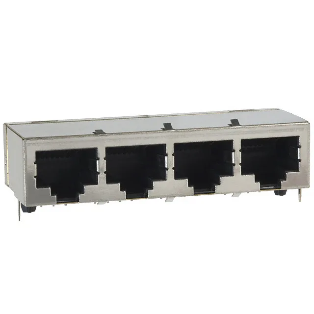
It terminates via through-hole solder tails and carries a Cat5 rating, which means it supports 100 MHz signaling — the standard for 100BASE-TX and 1000BASE-T Ethernet links in structured cabling. The EMI finger shield bleeds common-mode noise to the chassis ground before it reaches the PHY, so this jack belongs on a board-edge layout where the cable enters an industrial controller, a PoE switch, or a test-equipment front panel.
Shielding and Board-Mounting Details
The shield is a full metal shell with integrated EMI fingers that contact the panel or chassis cutout — no separate ground clip needed. The housing is molded from PCT/polyester, a high-temperature thermoplastic that survives lead-free reflow profiles without distorting the contact cavity alignment.
Contact Plating and Environmental Range
The jack does not contain an LED, so if your design needs link/activity indicators, plan for separate discrete LEDs on the PCB.
Cat5 vs Cat6 — What the Rating Means
The Cat5 rating certifies the jack for 100 MHz operation, which covers 10BASE-T, 100BASE-TX, and 1000BASE-T (Gigabit Ethernet over four-pair cabling). It does not carry the 250 MHz bandwidth required for Cat6 or the 500 MHz of Cat6a. If your application runs 10GBASE-T or requires the tighter NEXT (near-end crosstalk) margin of a Cat6 channel, this jack is not the right fit — you would need a Cat6-rated modular jack from the same TE portfolio. For standard office, industrial, or PoE applications up to 1 Gb/s, the Cat5 rating is sufficient and costs less than a higher-category part.