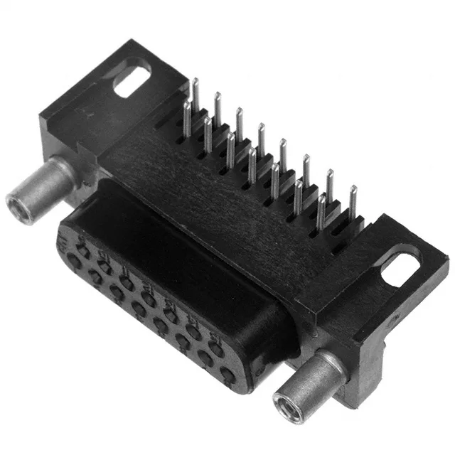
D-Sub Receptacle for Board-Edge I/O — 15 Positions, Right-Angle Solder
Screwlock and Mounting — What the Flange Feature Means for Your Assembly
The 5745396-2 includes female screwlocks (4-40) on the mating side — these are the threaded inserts that accept the male jack-screws on the mating D-sub plug. In a right-angle board-mount receptacle, the screwlocks provide the primary mechanical retention against cable strain and vibration. The backset spacing of 0.318" (8.08mm) sets the distance from the PCB edge to the mounting flange — verify this dimension against your enclosure cutout and panel thickness before layout.
Pin Layout and Mating — Standard DA Shell, 15 Positions in 2 Rows
The 5745396-2 uses the standard DA shell size (2, DA, A per the connector layout designation), which means 15 pins arranged in two rows — 8 in the top row, 7 in the bottom row. The pinout follows the industry-standard D-sub pattern: pin 1 in the top-left corner (looking at the solder side), pin 8 in the top-right, pin 9 in the bottom-left, and pin 15 in the bottom-right. This matches any standard 15-position D-sub plug with the same shell size. The female screwlocks (4-40) on the receptacle side mate with male jack-screws on the plug; if your mating half has a different locking mechanism (e.g., slide-lock or no hardware), the screwlocks can be removed or replaced with the appropriate hardware.