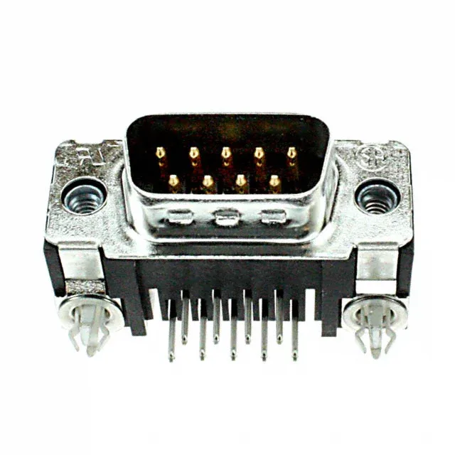
Right-Angle DB9 Plug with Board Locks
The steel shell carries tin plating and grounding indents that bleed shield current before it reaches the signal pins — a detail that matters in electrically noisy environments. Board locks on the mounting flanges anchor the connector during wave solder and resist shear from cable strain after mating. The flange uses the standard 4-40 threaded insert for mating with the receptacle's female screw-lock. The shell size is 1 (DE, E).
What the 6 A Rating Means for Signal vs Power Duty
Derate above 105°C per the manufacturer's curve.
Board Lock and Grounding Indents — Why They Matter
The board locks are integral to the mounting flange — they snap into plated through-holes on the PCB and hold the connector in place during wave soldering. Without them, the right-angle solder tails can shift as the board passes through the solder wave, causing cold joints or misalignment. The grounding indents on the steel shell mate with corresponding dimples on the receptacle shell, creating a low-impedance path for shield current before it reaches the signal pins. In a cabinet with multiple D-sub cables, that ground path reduces radiated emissions and susceptibility.