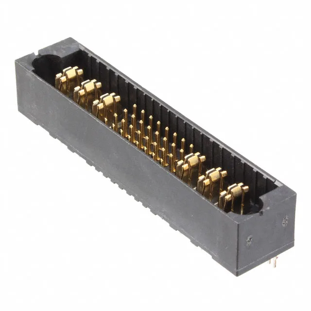
38-Position Power-and-Signal Header for Backplane Assembly
The TE Connectivity 6450820-3 is a 38-position MULTI-BEAM XL header that combines 32 signal contacts with 6 power blades in a single 4-row housing. Press-fit termination means this header goes into a plated through-hole board without a solder wave — the compliant pin compresses into the barrel, giving a gas-tight joint that survives backplane rework cycles.
Press-Fit Termination and Board Retention
Press-fit eliminates the solder process entirely — the compliant pin section is sized to cold-work the plated through-hole wall, creating a reliable interconnect without the thermal stress of wave or reflow soldering. This makes the 6450820-3 a natural fit for backplane assemblies where the PCB is thick and the connector rows are dense. The board lock is a molded-in barb that snaps into the board during insertion, providing the retention force needed to keep the header seated during handling before the mating connector is installed. The mating guide is a chamfered shroud on the housing that funnels the receptacle into alignment — critical when the header is buried in a card cage and the operator cannot see the pin field.
Pinout: 32 Signal, 6 Power
The contact layout is 32 signal contacts and 6 power blades. The 4-row arrangement means the signal contacts occupy three rows and the power blades sit in the fourth, or the power blades are distributed across the rows — the manufacturer's application note defines the exact grid. All 38 positions are loaded; there are no optional empty cavities.