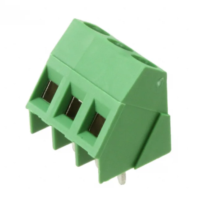
What This 3-Position Terminal Block Does
It terminates wires using a screw-driven rising cage clamp — the screw pushes a brass-tin-plated clamp up against the conductor, gripping it against the current bar. The housing is green polyamide 6/6, which often signals a ground or chassis connection in European-style schematics, though it is not a mandatory assignment — just a visual cue. The 35° (145°) angle with the board lets the wire entry sit low, useful when the enclosure lid clears the connector by only a few millimetres.
The rising cage clamp accepts solid or stranded wire from 30 AWG up to 12 AWG. Strip the insulation about 7 mm, insert the bare conductor into the clamp opening, and tighten the M3 screw to 0.79 Nm (7.0 Lb-In). The brass-nickel-plated screw drives a brass-tin-plated clamp that rises vertically, trapping the wire against the tin-plated brass current bar. The clamp does not rotate, so it will not twist or nick fine-stranded wire during termination. The interlocking side feature lets you key adjacent blocks together to build a multi-position assembly without a separate rail — the side dovetails snap together before soldering.
The 5.00 mm pitch sets the hole pattern — each position needs a 1.3 mm to 1.6 mm plated-through hole depending on the pin diameter, though the exact footprint is in the product drawing. The 35° wire exit means the conductor runs at an angle to the board surface, not parallel to it, so the keep-out zone on the component side is a triangle rather than a rectangle. The through-hole pins anchor the block during wave solder; the PA66 housing handles the soldering thermal cycle without distortion. The single-level design means all three terminations are on the same plane, so wire routing is straightforward — no staggered levels to manage.