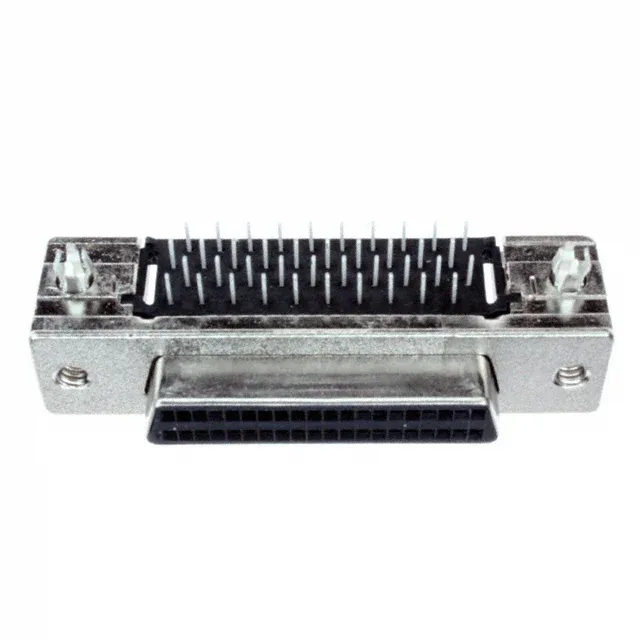
TE Connectivity AMP Connectors 5787170-4

TE Connectivity 5787170-4 AMPLIMITE .050 III D-Sub

MPN 5787170-4
Active

TE Connectivity AMPLIMITE.050 III D-sub receptacle, 40 positions, 2 rows, right-angle solder termination, gold-plated contacts, shielded, board locks, UL94 V-0, 1 A, 30 V.

$9.9800 Ref. price · indicative, final on quote
Dispatch SLA24-48h Global Rush
Quality CheckOriginal Seal & Physical QC
RoHSROHS3 Compliant
IncotermsDAP / DDP Available
SeriesAMPLIMITE .050 III
Source DocumentedChannel stated on listing & quote
Condition PhotosReal unit photos / video on request
WhatsApp AnswersFast human replies for stock & sourcing questions
Worldwide DispatchDHL/FedEx — transit quoted per order
Independent supplier — new & surplus connector stock· Listing updated Aug 2026

Specifications

5787170-4 key specifications
ParameterValue
SeriesAMPLIMITE .050 III
TypeSignal
MountingBoard Edge, Through Hole, Right Angle
Connector typeReceptacle, Female Sockets
Voltage rating30V
Current rating1A
Shell size, connector layout0.050 Pitch x 0.100 Row to Row
Operating temperature-55°C ~ 105°C
ColorBlack
Contact materialPhosphor Bronze
Dielectric materialThermoplastic
Shell material, finishSteel, Nickel Plated

All specifications

5787170-4 additional specifications
ParameterValue
Material flammability ratingUL94 V-0
PackageTube
FeaturesBoard Lock, Shielded
TerminationSolder
Contact finishGold
Flange featureHousing/Shell (4-40)
Rows2
Backset spacing0.146\" (3.71mm)
Positions40

Product details

The TE Connectivity 5787170-4 is a 40-position D-sub receptacle from the AMPLIMITE.050 III series, designed for board-edge mounting with a right-angle solder termination. It carries gold-plated contacts rated 1 A per circuit at 30 V — a signal-density interconnect for applications where the 0.050-inch pitch keeps the footprint compact. The shielded shell with nickel-plated steel construction and integral board locks gives this connector a place in EMI-sensitive equipment where mechanical retention and grounding are needed at the board edge.

Board Lock and Shield — What They Mean for Assembly

For a board layout engineer, the 0.146-inch backset spacing sets the distance from the board edge to the mounting flange — check this against your enclosure clearance before committing the footprint.

No official cross-reference or pin-compatible equivalent is listed; the 40-position count and 0.050-inch pitch define the footprint, so confirm the mating half and BOM position count before specifying.

MPN
5787170-4