The 10125839-06RAEHLF: The header is surface-mount, right-angle, with solder termination. The Solder Retention feature provides additional mechanical hold during reflow and against cable strain. The 1.20 mm pitch demands a precise PCB footprint — the board layout engineer should confirm the pad pattern against the product drawing to avoid routing conflicts with adjacent components.
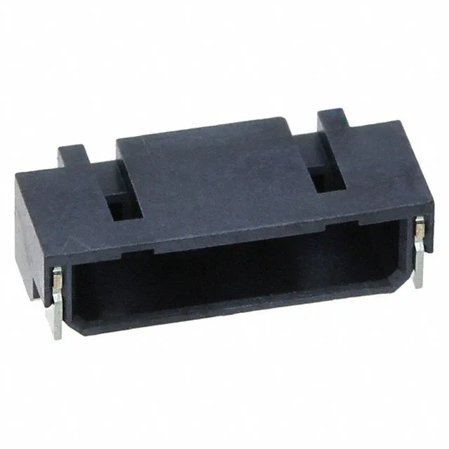
10125839-06RAEHLF SMT Right-Angle Header, 6 Pos, 1.2mm Pitch
MPN10125839-06RAEHLF
Active
Amphenol ICC (FCI) 10125839-06RAEHLF, 6-position, 1.20mm pitch, surface-mount right-angle shrouded header, gold-plated contacts, detent lock, UL94 V-0, Tape & Reel.
$0.5200Ref. price · indicative, final on quote
RoHSRoHS Compliant
Source DocumentedChannel stated on listing & quote
Condition PhotosReal unit photos / video on request
WhatsApp AnswersFast human replies for stock & sourcing questions
Worldwide DispatchDHL/FedEx — transit quoted per order
Independent supplier — new & surplus connector stock· Listing updated Aug 2026
Specifications
| Parameter | Value |
|---|---|
| Type | Tab |
| Mounting | Surface Mount, Right Angle |
| Connector type | Receptacle |
| Fastening type | Detent Lock |
| Contact material | Copper Alloy |
| Insulation color | Black |
| Insulation height | 0.098\" (2.50mm) |
| Insulation material | Liquid Crystal Polymer (LCP), Halogen Free |
| Material flammability rating | UL94 V-0 |
| Style | Board to Cable/Wire |
| Package | Tape & Reel (TR); Cut Tape (CT) |
| Features | Solder Retention |
All specifications
| Parameter | Value |
|---|---|
| Shrouding | Shrouded - 4 Wall |
| Termination | Solder |
| Contact shape | Rectangular |
| Rows | 1 |
| Pitch | 0.047\" (1.20mm) |
| Positions | 6 |
| Contact finish - post | Gold |
| Contact finish - mating | Gold |
| Contact finish thickness - post | 2.00µin (0.051µm) |
| Contact finish thickness - mating | 3.90µin (0.099µm) |
Product details
Frequently asked questions
Is 10125839-06RAEHLF RoHS compliant?
Yes, the 10125839-06RAEHLF is RoHS compliant per the manufacturer's listing.
What is the recommended PCB layout for 10125839-06RAEHLF?
The connector is a 6-position, 1.20 mm pitch, single-row, right-angle SMT header. The PCB footprint should match the product drawing for pad dimensions and keep-out zones. The Solder Retention feature helps anchor the part during reflow, but the board layout engineer should verify the pad pattern against the official drawing to ensure proper alignment and solder joint reliability.