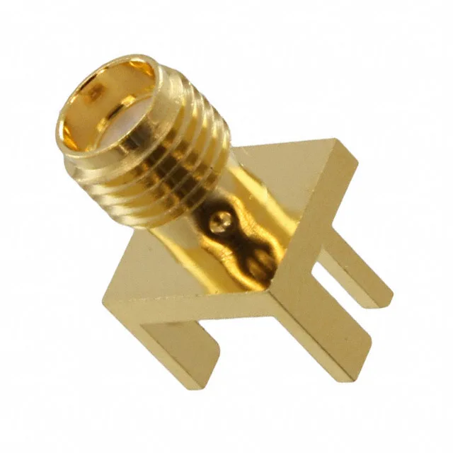
132410-10 — Amphenol product photo

Amphenol RF 132410-10 SMA Receptacle, 50 Ohm, 18 GHz

MPN132410-10
Active

Amphenol RF SMA receptacle, female socket, 50 Ohm, 18 GHz max, gold-plated brass body, board edge/end launch mount, solder termination, bulk package.

$10.6900Ref. price · indicative, final on quote
StockContact for availability
MOQ1 pcs
  • New & original stockTraceable channels only — no mixed lots, no re-taped reels.
  • Factory packaging where availableSealed reels, trays and bags; cut quantities always stated on the quote.
  • Photo-verified countsEvery line counted and photographed before the box closes.
  • PayPal buyer protectionPay by T/T, PayPal or Payoneer — card payments covered end to end.

Specifications

132410-10 Technical Specifications
ParameterValue
Mounting typeBoard Edge, End Launch
Connector typeReceptacle, Female Socket
Fastening typeThreaded
Frequency - max18 GHz
Operating temperature-65°C~165°C
Body materialBrass
Housing colorGold
Dielectric materialPolytetrafluoroethylene (PTFE)
Center contact materialBeryllium Copper
PackageBulk
Impedance50Ohm
Body finishGold
Mating cycles500
Number of ports1
Shield terminationSolder
Contact terminationSolder
Center contact platingGold

Product details

SMA End-Launch Receptacle for 18 GHz Signal Paths

It is a single-port, 50 Ohm design rated to 18 GHz, placing it at the top end of standard SMA performance — most SMA connectors top out around 12.4 or 18 GHz, and this one holds the full 18 GHz bandwidth.

The 18 GHz frequency maximum means this connector passes signals up to Ka-band without a significant impedance bump — useful for microwave links, radar IF stages, and high-speed digital clocks where the edge rate pushes into the GHz range. The 500-cycle rating comes from the gold-on-gold contact interface (gold-plated centre contact in a gold-plated body); that is enough for a production test point or a field-replaceable module that sees regular connect/disconnect, but not for a daily-use lab cable that gets cycled hundreds of times a week. For that duty, look at an SMA with a higher cycle spec or a threaded coupling that distributes wear differently.

Board Layout: End-Launch Footprint and Solder Termination

End-launch mounting places the connector body flush with the board edge, so the centre pin and ground legs solder directly to traces on the top layer. The shield termination is solder — no press-fit or snap-in retention — so the board footprint must include solder pads for the four ground legs and the centre pin. The body is threaded (fastening type: threaded), so the mating SMA plug screws on; the panel or bracket needs clearance for a wrench or torque tool. The PTFE dielectric inside the connector body sets the impedance, so the PCB launch geometry (trace width, ground clearance, dielectric height) must match 50 Ohm to avoid a reflection at the interface.

Frequently asked questions

What is the impedance of the 132410-10?

The 132410-10 is a 50 Ohm connector, the standard impedance for RF and microwave signal paths.

Is the 132410-10 a threaded connector?

Yes, the fastening type is threaded — the mating SMA plug screws onto the receptacle for a secure, vibration-resistant connection.

What is the connector type of the 132410-10?

The 132410-10 is an SMA receptacle with a female socket contact, designed for board edge or end launch mounting.