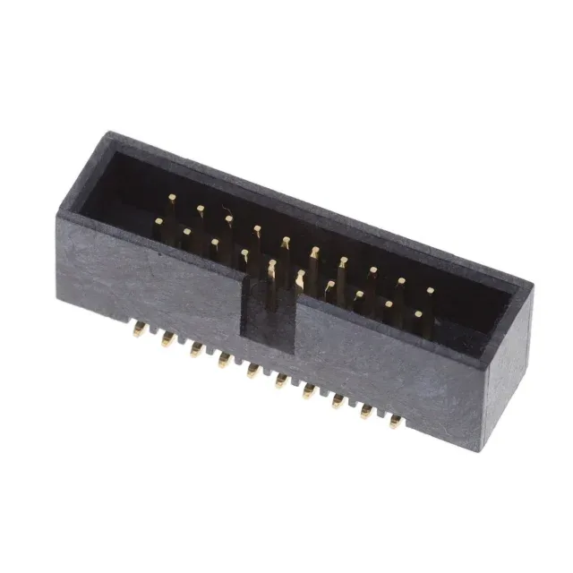
The 20021521-00020T1LF: The 0.050" (1.27mm) pitch is the tightest common spacing for a board-to-wire header — it drives the PCB footprint and the trace fan-out between rows. At 20 positions in two rows, the row-to-row spacing is also 1.27mm, so the board layout engineer needs a 4-layer board to route all signals out without necking down trace widths below 0.15mm. Rated 1A per contact at 125VAC — this is a signal-level current, not power delivery. For a field-service application cycled quarterly, the gold flash will wear through after roughly 50 cycles, exposing the copper alloy base.
Board-to-Cable/Wire Style — Harness Design Constraints
The harness designer must specify the matching Minitek127 crimp terminal and receptacle housing — the 1.27mm pitch limits the wire gauge to 28-30 AWG for reliable crimp retention. The SMD termination with solder tails means the header is reflow-soldered to the PCB. The insulation height of 0.220" (5.60mm) sets the z-height budget above the board — the mating receptacle adds another ~4mm, so the total mated stack height is roughly 9.6mm. The keying slot prevents mismating with non-keyed receptacles in the same series.
No stock-holding claim; the part is procured per request.