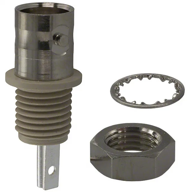
50 Ohm Isolated BNC Jack — 4 GHz, Solder Cup Termination
The 31-10: The key feature here is the isolated design — the connector body is electrically isolated from the mounting panel, which breaks ground loops in test setups and instrumentation where the shield path needs to float relative to chassis ground. Termination is solder cup — the center conductor and braid are hand-soldered to the contact and shield, not crimped. That means cable prep is manual: strip the coax to the right lengths, tin the center conductor, flow solder into the cup, and dress the braid to the body. The silver-plated phosphor bronze center contact gives low contact resistance at first mate, but silver tarnishes over time in humid or sulfurous air; for a test bench connector that gets mated a few hundred times and lives indoors, it's fine. The 500 mating cycles confirm this is a moderate-duty part — not a daily-connect production interface. Panel mounting uses a rear-side nut: the connector body passes through the panel from the outside, and the hex nut and lockwasher (included in the kit —) tighten from inside the enclosure. The bulkhead hole diameter is not listed in the spec, but standard BNC panel-mount jacks typically need a 0.500-inch (12.7 mm) hole — confirm against the product drawing before cutting the panel.
50 Ohm Impedance — Cable Match Matters
This is a 50 Ohm connector, not 75 Ohm. The 50 Ohm impedance means it's designed to work with 50 Ohm coax cables — RG-58, RG-174, RG-213, LMR-195, and similar. A 75 Ohm BNC (common in video/CCTV) has a different center contact diameter and dielectric geometry; mating a 50 Ohm jack to a 75 Ohm plug will cause an impedance mismatch that degrades return loss above a few hundred MHz. The 31-10 is the 50 Ohm isolated version in Amphenol's BNC line; the non-isolated sibling (31-2) shares the same body and termination but lacks the isolation feature, so the body is electrically common with the panel ground. If your application requires the shield to float, the 31-10 is the correct pick.