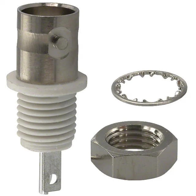
The 31-10-RFX: It includes the connector, a lockwasher, and a nut — three pieces that cover the mounting hardware in one order code.
RF Performance and Signal Path Limits
The 4 GHz ceiling means it covers the full VHF/UHF band and well into the lower microwave range; above that frequency the BNC interface geometry starts to radiate and the insertion loss climbs past the rated 0.2 dB. The silver-plated phosphor bronze center contact keeps the RF path low-loss and oxidation-resistant for the signal levels this connector sees.
Mounting and Termination — What Ships in the Bag
The 31-10-RFX is a rear-side-nut bulkhead mount: the jack body passes through the panel hole, the lockwasher and nut tighten from the rear. The shield termination is solder — you tin the braid and flow it into the cup — and the center contact uses a solder cup as well, so this is a hand-assembly job, not a crimp operation.
Rated for 500 mating cycles — that is a solid number for a bayonet-lock connector on a test panel or a piece of portable field gear that gets connected and disconnected a few times a week. The silver plating on the center contact helps here: silver has good cycle life under moderate insertion force, and the bayonet lock distributes the mating load evenly across the coupling nut rather than the center pin. After 500 cycles the contact resistance may start to drift; for higher-cycle applications a gold-plated BNC would be the better call.
Voltage and Environment — What the 500 V Rating Means
In practice, at 4 GHz the RF voltage swing is usually well below 500 V peak, so the voltage rating is a safety margin for DC bias or low-frequency AC that might ride on the RF line.