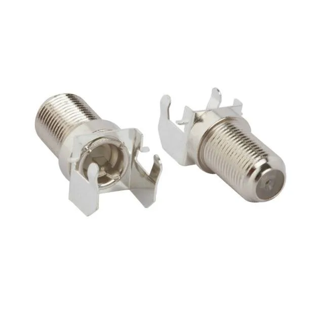
F-Type Receptacle for 75 Ohm Board-Edge RF
The 531-40101: The 75 Ohm impedance and 2 GHz frequency ceiling make it a direct fit for digital video distribution, cable TV modems, set-top boxes, and broadband RF stages where the system impedance is 75 Ohms, not the 50 Ohm standard used in telecom and test equipment. A polypropylene dielectric centres the contact and sets the 75 Ohm characteristic impedance. Two features matter during assembly. First, the board lock — a pair of solderable tabs that anchor the connector body to the PCB before the centre contact is soldered. Without them, the torque from tightening the F connector nut can lift the ground legs off the board. Second, the shield termination is solder — the outer braid of the coax solders directly to the body's solder tab, not a crimp ferrule, which is common on PCB-mount F jacks where the installer has access to both sides of the board.
The 531-40101 mounts at the PCB edge with the signal launch parallel to the board. The end-launch footprint means the centre contact solder tab extends beyond the board edge — the PCB layout must include a cut-out or notch for the connector body to sit flush. The board lock pins go into plated through-holes and are soldered on the opposite side. The shield tab and centre contact are both solder-terminated; the centre tab takes the coax centre conductor, and the shield tab takes the braid. The polypropylene dielectric holds its dielectric constant across that range, so the 75 Ohm impedance stays within tolerance. The connector is shipped in a tray — one part per pocket, no tape-and-reel, which is typical for hand-loaded board assembly or low-volume production.