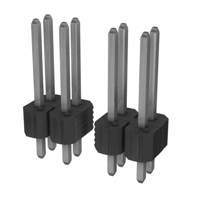
At a 0.100" (2.54 mm) mating pitch with matching 0.100" row spacing, this through-hole header provides a dense but routable footprint for parallel PCB stacking or wire-to-board transition via a mating receptacle. Rated 5 A per circuit at 110 V, the tin-plated phosphor bronze contacts carry 100.0 µ" (2.54 µm) of tin on the mating surface — a thickness that handles moderate insertion cycles in clean, indoor environments without the cost of gold.
The 110 V voltage rating provides headroom for typical 48 V telecom or 24 V industrial supplies without derating concerns. The tin plating at 100 µ" is the governing factor for contact reliability: tin is suited for 25–50 mating cycles in non-corrosive environments, and the 100 µ" thickness resists wear-through longer than the thinner 30–50 µ" tin finishes common on commodity headers.
Board footprint and mechanical fit
The 0.100" pitch and 0.100" row spacing produce a 0.100" x 0.100" grid that matches the industry-standard Berg/post header footprint — the same pattern used by legacy 0.025"-square pin headers. The overall contact length of 0.525" (13.34 mm) splits into a 0.318" (8.08 mm) mating section and a 0.107" (2.71 mm) solder post. The 0.107" post length is short — it suits boards around 0.062" thick but may not protrude far enough for thicker 0.093" boards or for wave-solder fillet formation on heavy copper planes. The insulation height of 0.100" (2.54 mm) leaves the pins exposed above the black UL94 V-0 housing, so the mating receptacle must provide the shroud for pin alignment and protection.