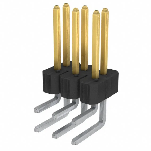
It uses a standard 0.100" (2.54 mm) pitch and row spacing, making it footprint-compatible with a wide range of existing PCB layouts and mating receptacles. Each male pin is rated for 5 A, a signal-level current that keeps the temperature rise within the UL94 V-0 housing limits. The 30.0 µin (0.76 µm) gold or GXT™ plating on the mating surface provides the corrosion resistance and cycle life for repeated mating in environments where tin would fret — think field-serviceable assemblies or test fixtures.
The 0.100" pitch and 0.100" row spacing place this header on the industry-standard grid. The 0.318" (8.08 mm) mating pin length gives enough wipe to seat through a typical receptacle's contact beam at the worst-case stack tolerance. The 0.110" (2.79 mm) solder post length is sized for standard 1.6 mm PCBs — the post protrudes enough for a reliable fillet without bottoming out in a plated through-hole. For a 6-position, 2-row layout, the footprint occupies about 0.300" along the board edge, leaving room for routing between pads at this pitch.